HEATING / AIR CONDITIONING AIR CONDITIONING SYSTEM(for Gasoline Model) ECO Switch Circuit
DESCRIPTION
The ECO drive mode control is activated for the air conditioning system by operating the integration control and panel assembly (ECO switch).
When the air conditioning system control cannot be performed while in ECO drive mode due to a malfunction etc., the following causes are possible.
| Malfunction Status | Factor |
|---|---|
·
Even if ECO drive mode is selected, the air vent cannot be controlled ·
Even if ECO drive mode is not selected, the air vent cannot be controlled |
·
Air conditioning amplifier assembly malfunction ·
Integration control and panel assembly (ECO switch) malfunction ·
Harness or connector |
WIRING DIAGRAM
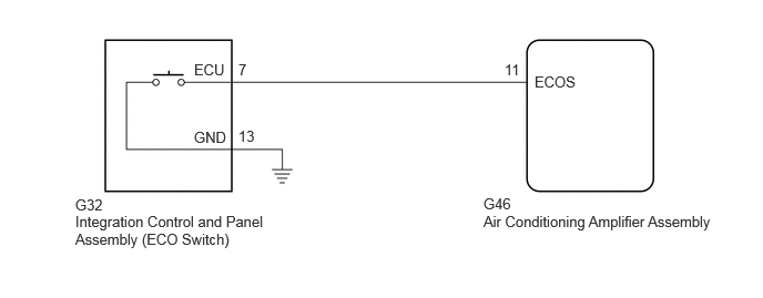
PROCEDURE
Read the Data List according to the display on the GTS.
- Body Electrical > Air Conditioner > Data List
-
Tester Display Measurement Item Range Normal Condition Diagnostic Note ECO Switch Integration control and panel assembly (ECO switch) OFF or ON ON: Integration control and panel assembly (ECO switch) being turned and held at ECO position
OFF: Integration control and panel assembly (ECO switch) not turned-
- Body Electrical > Air Conditioner > Data List
-
Tester Display ECO Switch - 50003 450 282
- OK:
Integration control and panel assembly (ECO switch) condition displayed on the GTS changes with the actual switch operation.
- Result:
Proceed to OK NG
OK
NG
- Result:
Proceed to OK NG
OK
NG
Disconnect the G32 integration control and panel assembly (ECO switch) connector.
Disconnect the G46 air conditioning amplifier assembly connector.
Measure the resistance according to the value(s) in the table below.
- Standard Resistance:
Tester Connection Condition Specified Condition G32-7 (ECU) - G46-11 (ECOS) Always Below 1 Ω G32-13 (GND) - Body ground Always Below 1 Ω G32-7 (ECU) or G46-11 (ECOS) - Other terminals and body ground Always 10 kΩ or higher
- Result:
Proceed to OK NG
OK
NG