HEATING / AIR CONDITIONING AIR CONDITIONING SYSTEM(for Gasoline Model) B143B7F Air Inlet Damper Control Servo Motor Actuator Stuck Off
DESCRIPTION
The No. 1 blower damper servo sub-assembly sends pulse signals to inform the air conditioning amplifier assembly of the damper position. The air conditioning amplifier assembly activates the motor (normal or reverse) based on these signals to move the air inlet damper to the appropriate position, which controls the air inlet switching.
The air conditioning amplifier assembly communicates with the servo through a communication/driver IC and wiring assembly called the air conditioning harness assembly.
| DTC No. | Detection Item | DTC Detection Condition | Trouble Area | Memory |
|---|---|---|---|---|
| B143B7F | Air Inlet Damper Control Servo Motor Actuator Stuck Off | Diagnosis Condition:
No. 1 blower damper servo sub-assembly operating Malfunction Status:
Damper servo operation request signals are output but the damper position sensor value does not change or abnormal Detection Time:
Continuously for 30 seconds or more |
·
No. 1 blower damper servo sub-assembly ·
Air conditioning harness assembly ·
Blower assembly ·
Air conditioning amplifier assembly |
Memorized |
| Vehicle Condition | |||
|---|---|---|---|
| Pattern 1 | Pattern 2 | ||
| Diagnosis Condition | No. 1 blower damper servo sub-assembly operating | ○ | ○ |
| Malfunction | Damper servo operation request signals are output but the damper position sensor value does not change | ○ | - |
| Damper servo operation request signals are output but the damper position sensor value is abnormal | - | ○ | |
| Detection Time | Continuously for 30 seconds or more | Continuously for 30 seconds or more | |
| Trip Count | 1 trip | 1 trip | |
- HINT:
-
If the conditions of either of these patterns are detected, a DTC will be stored
WIRING DIAGRAM
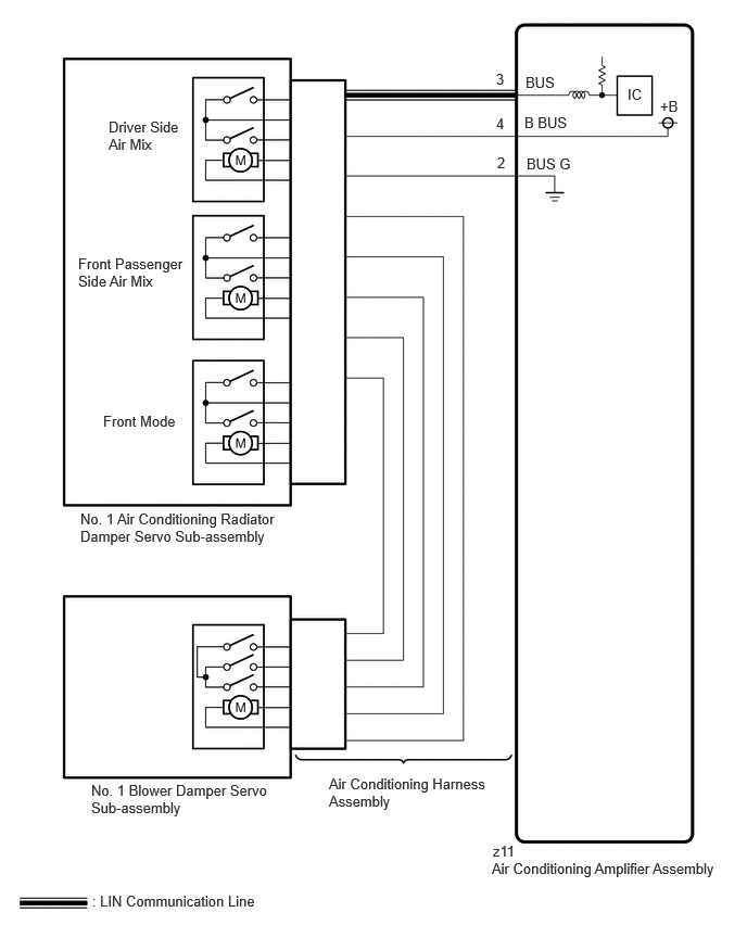
CAUTION / NOTICE / HINT
- NOTICE:
- ·
This DTC is also output for the damper link, damper lock, etc. Before performing inspection, perform servomotor initialization and check that there are no mechanical malfunctions.
·This DTC is also output when servomotor initialization has failed. When servomotor initialization has failed, repair any malfunctions and perform servomotor initialization again.
PROCEDURE
Check for DTCs.
- Body Electrical > Air Conditioner > Trouble Codes
- 50001 450
- Result:
Result Proceed to B143B7F is output A DTCs in conjunction with No. 1 air conditioning radiator damper servo sub-assembly are output at same time B
A
B
Check that the No. 1 blower damper servo sub-assembly is installed correctly.
- HINT:
- OK:
The No. 1 blower damper servo sub-assembly is installed correctly.
- Result:
Proceed to OK NG
OK
NG
Check for a wire harness caught between the links of the motors and dampers.
- OK:
No wire harnesses are caught between the links of the motors and dampers.
- Result:
Proceed to OK NG
OK
NG
Using the GTS, perform the following Active Test and read the Data List value.
- Body Electrical > Air Conditioner > Active Test
-
Tester Display Measurement Item Control Range Diagnostic Note Air Inlet Damper Control Servo Motor No. 1 blower damper servo sub-assembly operation 128 to 384 Operates between 235 to 258 pulses
- Body Electrical > Air Conditioner > Data List
-
Tester Display Measurement Item Range Normal Condition Diagnostic Note Air Inlet Damper Control Servo Motor Actual Pulse No. 1 blower damper servo sub-assembly actual pulse Min: 128
Max: 384·Recirculation: 258 (pulse)
·Fresh: 235 (pulse)
-
- Body Electrical > Air Conditioner > Active Test
-
Active Test Display Air Inlet Damper Control Servo Motor -
Data List Display Air Inlet Damper Control Servo Motor Actual Pulse - 50004 450 32 213
- OK:
The value of the Data List changes in accordance with the operation of the Active Test.
- Result:
Proceed to OK NG
OK
NG
Using the GTS, perform the following Active Test and read the Data List value.
- Body Electrical > Air Conditioner > Active Test
-
Tester Display Measurement Item Control Range Diagnostic Note Air Inlet Damper Control Servo Motor No. 1 blower damper servo sub-assembly operation 128 to 384 Operates between 235 to 258 pulses
- Body Electrical > Air Conditioner > Data List
-
Tester Display Measurement Item Range Normal Condition Diagnostic Note Air Inlet Damper Control Servo Motor Target Pulse No. 1 blower damper servo sub-assembly target pulse Min: 128
Max: 384·Recirculation: 258 (pulse)
·Fresh: 235 (pulse)
- Air Inlet Damper Control Servo Motor Actual Pulse No. 1 blower damper servo sub-assembly actual pulse Min: 128
Max: 384·Recirculation: 258 (pulse)
·Fresh: 235 (pulse)
-
- Body Electrical > Air Conditioner > Active Test
-
Active Test Display Air Inlet Damper Control Servo Motor -
Data List Display Air Inlet Damper Control Servo Motor Target Pulse Air Inlet Damper Control Servo Motor Actual Pulse - 50004 450 32 212,213
- OK:
The target pulse value of the Data List matches the actual pulse.
- Result:
Proceed to OK NG
OK
NG
- HINT:
- Result:
Proceed to NEXT
NEXT
Using the GTS, perform the following Active Test and read the Data List value.
- Body Electrical > Air Conditioner > Active Test
-
Tester Display Measurement Item Control Range Diagnostic Note Air Inlet Damper Control Servo Motor No. 1 blower damper servo sub-assembly operation 128 to 384 Operates between 220 to 256 pulses
- Body Electrical > Air Conditioner > Data List
-
Tester Display Measurement Item Range Normal Condition Diagnostic Note Air Inlet Damper Control Servo Motor Actual Pulse No. 1 blower damper servo sub-assembly actual pulse Min: 128
Max: 384·Recirculation: 256 (pulse)
·Fresh: 220 (pulse)
-
- Body Electrical > Air Conditioner > Active Test
-
Active Test Display Air Inlet Damper Control Servo Motor -
Data List Display Air Inlet Damper Control Servo Motor Actual Pulse - 50004 450 32 213
- OK:
The value of the Data List changes in accordance with the operation of the Active Test.
- Result:
Proceed to OK NG
OK
NG
Using the GTS, perform the following Active Test and read the Data List value.
- Body Electrical > Air Conditioner > Active Test
-
Tester Display Measurement Item Control Range Diagnostic Note Fr Control Rear Air Outlet Damper Servo Motor No. 2 air conditioning radiator damper servo sub-assembly operation 128 to 384 Operates between 158 to 260 pulses
- Body Electrical > Air Conditioner > Data List
-
Tester Display Measurement Item Range Normal Condition Diagnostic Note Front Control Rear Air Outlet Damper Control Servo Motor Actual Pulse No. 2 air conditioning radiator damper servo sub-assembly actual pulse Min: 128
Max: 384·FACE: 260 (pulse)
·FOOT-R, D, O, F/D: 223 (pulse)
·B/L: 212 (pulse)
·FOOT-F: 182 (pulse)
·D/F: 177 (pulse)
·DEF/S-FLOW: 158 (pulse)
-
- Body Electrical > Air Conditioner > Active Test
-
Active Test Display Fr Control Rear Air Outlet Damper Servo Motor -
Data List Display Front Control Rear Air Outlet Damper Control Servo Motor Actual Pulse - 50004 450 49 247
- OK:
The value of the Data List changes in accordance with the operation of the Active Test.
- Result:
Proceed to OK NG
OK
NG
Pre-procedure1
Remove the No. 1 blower damper servo sub-assembly.
- HINT:
Procedure1
Operate the dampers by hand.
- OK:
The dampers are easily operated by hand.
- Result:
Proceed to OK NG
Post-procedure1
None
OK
NG