RM36D0EC _59 Vehicle Exterior _083099 MIRROR (EXT) _0400988 POWER MIRROR CONTROL SYSTEM J

MIRROR (EXT)  POWER MIRROR CONTROL SYSTEM  Power Retractable Mirrors do not Operate with Power Retract Mirror Switch  


DESCRIPTION

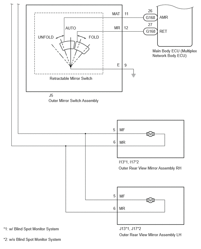
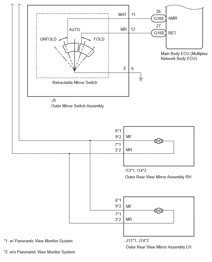
When the outer mirror switch assembly is operated, the mirror retract/return signal is sent to the main body ECU (multiplex network body ECU) and then to power distribution box assembly via CXPI communication.

The power distribution box assembly retracts or returns the outer rear view mirror assemblies based on the signal.

WIRING DIAGRAM

for SFTM Made:
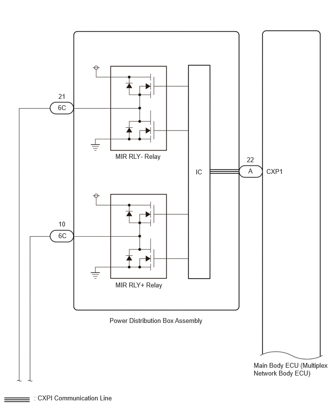

E445358E04
5.313,3.573 5.469,3.771 0.156,0.198 10 false A 5.281,3.333 5.594,3.531 0.313,0.198 10 false 22 5.698,3.583 6.313,3.781 0.615,0.198 10 false CXP1 4.188,3.594 4.5,3.792 0.313,0.198 10 false IC 2.469,3.26 3.51,3.479 1.042,0.219 10 false MIR RLY- Relay 2.469,6.01 3.51,6.229 1.042,0.219 10 false MIR RLY+ Relay 1.24,2.219 1.552,2.417 0.313,0.198 10 false 6C 1.25,1.979 1.563,2.177 0.313,0.198 10 false 21 1.25,4.958 1.563,5.156 0.313,0.198 10 false 6C 1.25,4.708 1.563,4.906 0.313,0.198 10 false 10 5.427,7.729 7.052,8.125 1.625,0.396 10 false Main Body ECU (Multiplex Network Body ECU) 2.344,6.771 4.448,6.979 2.104,0.208 10 false Power Distribution Box Assembly 0.729,8.427 2.49,8.625 1.76,0.198 10 false : CXPI Communication Line

E465238E04
1.75,3.313 2.427,3.51 0.677,0.198 10 false J5 1.729,3.5 3.635,3.74 1.906,0.24 10 false Outer Mirror Switch Assembly 1.354,1.24 2.271,1.438 0.917,0.198 10 false UNFOLD 3.167,1.24 3.646,1.417 0.479,0.177 10 false FOLD 2.333,0.917 2.948,1.115 0.615,0.198 10 false AUTO 4.438,0.406 4.75,0.604 0.313,0.198 10 false 11 4.417,0.906 4.729,1.104 0.313,0.198 10 false 12 4.438,2.24 4.75,2.438 0.313,0.198 10 false 9 4,0.406 4.458,0.604 0.458,0.198 10 false MAT 4.073,0.906 4.354,1.104 0.281,0.198 10 false MR 4.177,2.229 4.375,2.427 0.198,0.198 10 false E 1.771,2.708 3.365,2.917 1.594,0.208 10 false Retractable Mirror Switch 5.438,1.729 7.073,2.135 1.635,0.406 10 false Main Body ECU (Multiplex Network Body ECU) 4.229,5.906 6.552,6.125 2.323,0.219 10 false Outer Rear View Mirror Assembly RH 4.25,8.281 6.573,8.5 2.323,0.219 10 false Outer Rear View Mirror Assembly LH 4.24,5.688 5.438,5.865 1.198,0.177 10 false I13*1, I17*2 4.26,8.063 5.521,8.25 1.26,0.188 10 false J13*1, J17*2 4.26,4.542 4.573,4.74 0.313,0.198 10 false MF 4.26,4.99 4.573,5.188 0.313,0.198 10 false MR 4.26,6.906 4.573,7.104 0.313,0.198 10 false MF 4.25,7.344 4.563,7.542 0.313,0.198 10 false MR 5.208,1.031 5.823,1.229 0.615,0.198 10 false G168 5.198,0.542 5.813,0.74 0.615,0.198 10 false G168 5.281,0.302 5.594,0.5 0.313,0.198 10 false 26 5.281,0.792 5.594,0.99 0.313,0.198 10 false 27 5.688,0.531 6.146,0.729 0.458,0.198 10 false AMR 5.688,1.031 6.146,1.229 0.458,0.198 10 false RET 0.125,8.073 3.417,8.323 3.292,0.25 10 false *1: w/ Blind Spot Monitor System 0.125,8.448 3.417,8.698 3.292,0.25 10 false *2: w/o Blind Spot Monitor System 4.042,6.896 4.208,7.104 0.167,0.208 10 false 5 4.042,7.344 4.271,7.552 0.229,0.208 10 false 6 4.042,4.979 4.229,5.167 0.188,0.188 10 false 6 4.031,4.542 4.583,4.844 0.552,0.302 10 false 5


for GTMC Made:


E445358E04
5.313,3.573 5.469,3.771 0.156,0.198 10 false A 5.281,3.333 5.594,3.531 0.313,0.198 10 false 22 5.698,3.583 6.313,3.781 0.615,0.198 10 false CXP1 4.188,3.594 4.5,3.792 0.313,0.198 10 false IC 2.469,3.26 3.51,3.479 1.042,0.219 10 false MIR RLY- Relay 2.469,6.01 3.51,6.229 1.042,0.219 10 false MIR RLY+ Relay 1.24,2.219 1.552,2.417 0.313,0.198 10 false 6C 1.25,1.979 1.563,2.177 0.313,0.198 10 false 21 1.25,4.958 1.563,5.156 0.313,0.198 10 false 6C 1.25,4.708 1.563,4.906 0.313,0.198 10 false 10 5.427,7.729 7.052,8.125 1.625,0.396 10 false Main Body ECU (Multiplex Network Body ECU) 2.344,6.771 4.448,6.979 2.104,0.208 10 false Power Distribution Box Assembly 0.729,8.427 2.49,8.625 1.76,0.198 10 false : CXPI Communication Line

E465238E05
1.75,3.313 2.427,3.51 0.677,0.198 10 false J5 1.729,3.5 3.635,3.74 1.906,0.24 10 false Outer Mirror Switch Assembly 1.354,1.24 2.271,1.438 0.917,0.198 10 false UNFOLD 3.167,1.24 3.646,1.417 0.479,0.177 10 false FOLD 2.333,0.917 2.948,1.115 0.615,0.198 10 false AUTO 4.438,0.406 4.75,0.604 0.313,0.198 10 false 11 4.417,0.906 4.729,1.104 0.313,0.198 10 false 12 4.438,2.24 4.75,2.438 0.313,0.198 10 false 9 4,0.406 4.458,0.604 0.458,0.198 10 false MAT 4.073,0.906 4.354,1.104 0.281,0.198 10 false MR 4.177,2.229 4.375,2.427 0.198,0.198 10 false E 1.771,2.708 3.365,2.917 1.594,0.208 10 false Retractable Mirror Switch 5.438,1.729 7.073,2.135 1.635,0.406 10 false Main Body ECU (Multiplex Network Body ECU) 4.229,5.906 6.552,6.125 2.323,0.219 10 false Outer Rear View Mirror Assembly RH 4.25,8.281 6.573,8.5 2.323,0.219 10 false Outer Rear View Mirror Assembly LH 4.24,5.688 5.438,5.865 1.198,0.177 10 false I13*1, I14*2 4.26,8.063 5.521,8.25 1.26,0.188 10 false J13*1, J14*2 4.26,4.542 4.573,4.74 0.313,0.198 10 false MF 4.26,4.99 4.573,5.188 0.313,0.198 10 false MR 4.26,6.906 4.573,7.104 0.313,0.198 10 false MF 4.25,7.344 4.563,7.542 0.313,0.198 10 false MR 3.896,6.896 4.24,7.125 0.344,0.229 10 false 9*2 3.885,7.354 4.438,7.656 0.552,0.302 10 false 3*2 5.208,1.031 5.823,1.229 0.615,0.198 10 false G168 5.198,0.542 5.813,0.74 0.615,0.198 10 false G168 5.281,0.302 5.594,0.5 0.313,0.198 10 false 26 5.281,0.792 5.594,0.99 0.313,0.198 10 false 27 5.688,0.531 6.146,0.729 0.458,0.198 10 false AMR 5.688,1.031 6.146,1.229 0.458,0.198 10 false RET 0.125,8.073 3.417,8.323 3.292,0.25 10 false *1: w/ Panoramic View Monitor System 0.125,8.448 3.417,8.698 3.292,0.25 10 false *2: w/o Panoramic View Monitor System 3.896,7.167 4.292,7.333 0.396,0.167 10 false 7*1 3.896,6.698 4.292,6.865 0.396,0.167 10 false 6*1 3.896,4.344 4.292,4.51 0.396,0.167 10 false 6*1 3.896,4.552 4.167,4.76 0.271,0.208 10 false 9*2 3.885,4.813 4.281,4.979 0.396,0.167 10 false 7*1 3.885,5 4.438,5.302 0.552,0.302 10 false 3*2


CAUTION / NOTICE / HINT

NOTICE:
·

The power mirror control system uses the CXPI communication system. Inspect the communication function by following How to Proceed with Troubleshooting. Troubleshoot the power mirror control system after confirming that the communication system is functioning properly.

Click hereVehicle Exterior>MIRROR (EXT)>POWER MIRROR CONTROL SYSTEM>HOW TO PROCEED WITH TROUBLESHOOTING

·

If the main body ECU (multiplex network body ECU) is replaced, refer to Service Bulletin.


PROCEDURE

1.READ VALUE USING GTS (OUTER MIRROR FOLD SWITCH)
a.

Read the Data List according to the display on the GTS.

Body Electrical > Main Body > Data List
Tester Display Measurement Item Range Normal Condition Diagnostic Note
Outer Mirror Fold Switch Outer mirror switch signal OFF/ON OFF: Outer mirror switch not in retract position
ON: Outer mirror switch assembly in retract position
-
Body Electrical > Main Body > Data List
Tester Display
Outer Mirror Fold Switch
50003 449 71
OK:

On the GTS screen, ON or OFF is displayed accordingly.


Result:
Proceed to
OK
NG


OK

2.CHECK VEHICLE CONDITION

NG

16.INSPECT OUTER MIRROR SWITCH ASSEMBLY
2.CHECK VEHICLE CONDITION
a.

Check the malfunctioning parts.


Result:
Result Proceed to
Both outer rear view mirror assemblies are malfunctioning A
Outer rear view mirror assembly LH is malfunctioning B
Outer rear view mirror assembly RH is malfunctioning C


A

3.PERFORM ACTIVE TEST USING GTS (MIRROR FOLD, MIRROR RETURN)

B

8.INSPECT OUTER REAR VIEW MIRROR ASSEMBLY LH

C

12.INSPECT OUTER REAR VIEW MIRROR ASSEMBLY RH
3.PERFORM ACTIVE TEST USING GTS (MIRROR FOLD, MIRROR RETURN)
a.

Perform the Active Test according to the display on the GTS.

Body Electrical > Main Body > Active Test
Tester Display Measurement Item Control Range Diagnostic Note
Mirror Fold Signal Retract mirror operation OFF/ON -
Mirror Return Signal Retract mirror operation OFF/ON -
Body Electrical > Main Body > Active Test
Tester Display
Mirror Fold Signal
50004 449 91
Body Electrical > Main Body > Active Test
Tester Display
Mirror Return Signal
50004 449 92
OK:

On the GTS screen, ON or OFF is displayed accordingly.


Result:
Proceed to
OK
NG


OK

NG

4.READ VALUE USING GTS (POWER RETRACT MIRROR INPUT SIGNAL)
a.

Read the Data List according to the display on the GTS.

Body Electrical > Power Distribution Box > Data List
Tester Display Measurement Item Range Normal Condition Diagnostic Note
Power Retract Mirror Input Signal Power retract mirror drive signal (Input) Stop, Retract, Return Stop: Not operate the outer mirror switch
Retract: Outer mirror switch in retract position
Return: Outer mirror switch in return position
-
Body Electrical > Power Distribution Box > Data List
Tester Display
Power Retract Mirror Input Signal
50003 475 1300
OK:

On the GTS screen, ON or OFF is displayed accordingly.


Result:
Proceed to
OK
NG


OK

NG

5.CHECK VEHICLE TYPE
a.

Check vehicle condition.


Result:
Result Proceed to
for GTMC Made A
for SFTM Made B


A

6.CHECK HARNESS AND CONNECTOR (POWER DISTRIBUTION BOX ASSEMBLY - OUTER REAR VIEW MIRROR ASSEMBLY RH)

B

7.CHECK HARNESS AND CONNECTOR (POWER DISTRIBUTION BOX ASSEMBLY - OUTER REAR VIEW MIRROR ASSEMBLY RH)
6.CHECK HARNESS AND CONNECTOR (POWER DISTRIBUTION BOX ASSEMBLY - OUTER REAR VIEW MIRROR ASSEMBLY RH)
a.

Disconnect the 6C power distribution box assembly connector.


b.

Disconnect the I13*1 or I14*2 outer rear view mirror assembly RH connector.

*1: w/ Panoramic View Monitor System

*2: w/o Panoramic View Monitor System


c.

Measure the resistance according to the value(s) in the table below.

Standard Resistance:
w/ Panoramic View Monitor System
Tester Connection Condition Specified Condition
6C-10 - I13-6 (MF) Always Below 1 Ω
6C-21 - I13-7 (MR) Always Below 1 Ω
6C-10 - Body Ground Always 10 kΩ or higher
6C-21 - Body Ground Always 10 kΩ or higher


w/o Panoramic View Monitor System
Tester Connection Condition Specified Condition
6C-10 - I14-9 (MF) Always Below 1 Ω
6C-21 - I14-3 (MR) Always Below 1 Ω
6C-10 - Body Ground Always 10 kΩ or higher
6C-21 - Body Ground Always 10 kΩ or higher


Result:
Proceed to
OK
NG


OK

NG

REPAIR OR REPLACE HARNESS OR CONNECTOR

7.CHECK HARNESS AND CONNECTOR (POWER DISTRIBUTION BOX ASSEMBLY - OUTER REAR VIEW MIRROR ASSEMBLY RH)
a.

Disconnect the 6C power distribution box assembly connector.


b.

Disconnect the I13*1 or I17*2 outer rear view mirror assembly RH connector.

*1: w/ Blind Spot Monitor System

*2: w/o Blind Spot Monitor System


c.

Measure the resistance according to the value(s) in the table below.

Standard Resistance:
w/ Blind Spot Monitor System
Tester Connection Condition Specified Condition
6C-10 - I13-5 (MF) Always Below 1 Ω
6C-21 - I13-6 (MR) Always Below 1 Ω
6C-10 - Body Ground Always 10 kΩ or higher
6C-21 - Body Ground Always 10 kΩ or higher


w/o Blind Spot Monitor System
Tester Connection Condition Specified Condition
6C-10 - I17-5 (MF) Always Below 1 Ω
6C-21 - I17-6 (MR) Always Below 1 Ω
6C-10 - Body Ground Always 10 kΩ or higher
6C-21 - Body Ground Always 10 kΩ or higher


Result:
Proceed to
OK
NG


OK

NG

REPAIR OR REPLACE HARNESS OR CONNECTOR

8.INSPECT OUTER REAR VIEW MIRROR ASSEMBLY LH

OK

9.CHECK VEHICLE TYPE

NG

9.CHECK VEHICLE TYPE
a.

Check vehicle condition.


Result:
Result Proceed to
for GTMC Made A
for SFTM Made B


A

10.CHECK HARNESS AND CONNECTOR (OUTER REAR VIEW MIRROR ASSEMBLY LH - POWER DISTRIBUTION BOX ASSEMBLY)

B

11.CHECK HARNESS AND CONNECTOR (OUTER REAR VIEW MIRROR ASSEMBLY LH - POWER DISTRIBUTION BOX ASSEMBLY)
10.CHECK HARNESS AND CONNECTOR (OUTER REAR VIEW MIRROR ASSEMBLY LH - POWER DISTRIBUTION BOX ASSEMBLY)
a.

Disconnect the 6C power distribution box assembly connector.


b.

Disconnect the J13*1 or J4*2 outer rear view mirror assembly LH connector.

*1: w/ Panoramic View Monitor System

*2: w/o Panoramic View Monitor System


c.

Measure the resistance according to the value(s) in the table below.

Standard Resistance:
w/ Panoramic View Monitor System
Tester Connection Condition Specified Condition
J13-6 (MF) - 6C-10 Always Below 1 Ω
J13-7 (MR) - 6C-21 Always Below 1 Ω

w/o Panoramic View Monitor System
Tester Connection Condition Specified Condition
J14-9 (MF) - 6C-10 Always Below 1 Ω
J14-3 (MR) - 6C-21 Always Below 1 Ω


Result:
Proceed to
OK
NG


OK

NG

REPAIR OR REPLACE HARNESS OR CONNECTOR

11.CHECK HARNESS AND CONNECTOR (OUTER REAR VIEW MIRROR ASSEMBLY LH - POWER DISTRIBUTION BOX ASSEMBLY)
a.

Disconnect the 6C power distribution box assembly connector.


b.

Disconnect the J13*1 or J17*2 outer rear view mirror assembly LH connector.

*1: w/ Blind Spot Monitor System

*2: w/o Blind Spot Monitor System


c.

Measure the resistance according to the value(s) in the table below.

Standard Resistance:
w/ Blind Spot Monitor System
Tester Connection Condition Specified Condition
J13-5 (MF) - 6C-10 Always Below 1 Ω
J13-6 (MR) - 6C-21 Always Below 1 Ω

w/o Blind Spot Monitor System
Tester Connection Condition Specified Condition
J17-5 (MF) - 6C-10 Always Below 1 Ω
J17-6 (MR) - 6C-21 Always Below 1 Ω


Result:
Proceed to
OK
NG


OK

NG

REPAIR OR REPLACE HARNESS OR CONNECTOR

12.INSPECT OUTER REAR VIEW MIRROR ASSEMBLY RH

OK

13.CHECK VEHICLE TYPE

NG

13.CHECK VEHICLE TYPE
a.

Check vehicle condition.


Result:
Result Proceed to
for GTMC Made A
for SFTM Made B


A

14.CHECK HARNESS AND CONNECTOR (OUTER REAR VIEW MIRROR ASSEMBLY RH - POWER DISTRIBUTION BOX ASSEMBLY)

B

15.CHECK HARNESS AND CONNECTOR (OUTER REAR VIEW MIRROR ASSEMBLY RH - POWER DISTRIBUTION BOX ASSEMBLY)
14.CHECK HARNESS AND CONNECTOR (OUTER REAR VIEW MIRROR ASSEMBLY RH - POWER DISTRIBUTION BOX ASSEMBLY)
a.

Disconnect the 6C power distribution box assembly connector.


b.

Disconnect the I13*1 or I14*2 outer rear view mirror assembly RH connector.

*1: w/ Panoramic View Monitor System

*2: w/o Panoramic View Monitor System


c.

Measure the resistance according to the value(s) in the table below.

Standard Resistance:
w/ Panoramic View Monitor System
Tester Connection Condition Specified Condition
I13-6 (MF) - 6C-10 Always Below 1 Ω
I13-7 (MR) - 6C-21 Always Below 1 Ω

w/o Panoramic View Monitor System
Tester Connection Condition Specified Condition
I14-9 (MF) - 6C-10 Always Below 1 Ω
I14-3 (MR) - 6C-21 Always Below 1 Ω


Result:
Proceed to
OK
NG


OK

NG

REPAIR OR REPLACE HARNESS OR CONNECTOR

15.CHECK HARNESS AND CONNECTOR (OUTER REAR VIEW MIRROR ASSEMBLY RH - POWER DISTRIBUTION BOX ASSEMBLY)
a.

Disconnect the 6C power distribution box assembly connector.


b.

Disconnect the I13*1 or I17*2 outer rear view mirror assembly RH connector.

*1: w/ Blind Spot Monitor System

*2: w/o Blind Spot Monitor System


c.

Measure the resistance according to the value(s) in the table below.

Standard Resistance:
w/ Blind Spot Monitor System
Tester Connection Condition Specified Condition
I13-5 (MF) - 6C-10 Always Below 1 Ω
I13-6 (MR) - 6C-21 Always Below 1 Ω

w/o Blind Spot Monitor System
Tester Connection Condition Specified Condition
I17-5 (MF) - 6C-10 Always Below 1 Ω
I17-6 (MR) - 6C-21 Always Below 1 Ω


Result:
Proceed to
OK
NG


OK

NG

REPAIR OR REPLACE HARNESS OR CONNECTOR

16.INSPECT OUTER MIRROR SWITCH ASSEMBLY

OK

17.CHECK HARNESS AND CONNECTOR (OUTER MIRROR SWITCH ASSEMBLY - MAIN BODY ECU [MULTIPLEX NETWORK BODY ECU])

NG

17.CHECK HARNESS AND CONNECTOR (OUTER MIRROR SWITCH ASSEMBLY - MAIN BODY ECU [MULTIPLEX NETWORK BODY ECU])
a.

Disconnect the J5 outer mirror switch assembly.


b.

Disconnect the G168 main body ECU (multiplex network body ECU).


c.

Measure the resistance according to the value(s) in the table below.

Standard Resistance:
Tester Connection Condition Specified Condition
J5-11 (MAT) - G168-26 (AMR) Always Below 1 Ω
J5-12 (MR) - G168-27 (RET) Always Below 1 Ω
J5-11 (MAT) or G168-26 (AMR) - Body ground Always 10 kΩ or higher
J5-12 (MR) or G168-27 (RET) - Body ground Always 10 kΩ or higher
J5-9 (E) - Body ground Always Below 1 Ω


Result:
Proceed to
OK
NG


OK

NG

REPAIR OR REPLACE HARNESS OR CONNECTOR