SUPPLEMENTAL RESTRAINT SYSTEMS SPIRAL CABLE REMOVAL
CAUTION / NOTICE / HINT
The necessary procedures (adjustment, calibration, initialization or registration) that must be performed after parts are removed, installed or replaced during the spiral cable with sensor sub-assembly removal/installation are shown below.
| Replaced Part or Performed Procedures | Necessary procedures | Effect/Inoperative Function When Necessary Procedures are not Performed | Link |
|---|---|---|---|
| Steering Sensor | Update ECU security key | - | ( 202405,999999,_V1,_083041,_0402305,RM100000002ISNL,) 202405,999999,_V1,_083041,_0402305,RM100000002ISNL,)
|
- HINT:
- ·
When the cable is disconnected/reconnected to the auxiliary battery terminal, systems temporarily stop operating. However, each system has a function that completes learning the first time the system is used.
-Learning completes when vehicle is driven
Effect/Inoperative Function When Necessary Procedures are not Performed Necessary Procedures Link Lane tracing assist system Drive the vehicle straight ahead at 35 km/h (22 mph) or more for 5 second or more. ( 201910,999999,_58,_083101,_0401880,RM100000001JE9I,)
Pre-collision system
-Learning completes when vehicle is operated normally
Effect/Inoperative Function When Necessary Procedures are not Performed Necessary Procedures Link Power back door function Fully close the back door by hand.
- HINT:
-
Initialization is not necessary if the above procedures are performed while the back door is closed.
( 202304,999999,_59,_083093,_0584672,RM1000000029PGT,)
Power door lock control system If the back door is locked and therefore cannot be opened, it is necessary to unlock the back door using the door control switch, electrical key transmitter sub-assembly switch. ( 202409,999999,_58,_083092,_0403003,RM100000002NS90,)
Air conditioning system After the ignition switch is turned to ON, the servo motor standard position is recognized -
| Replaced Part or Performed Procedures | Necessary procedures | Effect/Inoperative Function When Necessary Procedures are not Performed | Link |
|---|---|---|---|
| Steering Sensor | Update ECU security key | - | (202405,999999,_V1,_083041,_0402305,RM100000002ISNL,)
|
- HINT:
- ·
When the cable is disconnected/reconnected to the auxiliary battery terminal, systems temporarily stop operating. However, each system has a function that completes learning the first time the system is used.
-Learning completes when vehicle is driven
Effect/Inoperative Function When Necessary Procedures are not Performed Necessary Procedures Link Stop and start system Drive the vehicle until stop and start control is permitted (approximately 5 to 60 minutes). ( 202409,999999,_51,_083056,_0402418,RM100000002NSFO,)
Lane tracing assist system Drive the vehicle straight ahead at 15 km/h (10 mph) or more for 1 second or more. ( 201910,999999,_58,_083101,_0401880,RM100000001JE9I,)
Pre-collision system
-Learning completes when vehicle is operated normally
Effect/Inoperative Function When Necessary Procedures are not Performed Necessary Procedures Link *: w/ Power back door system
Power back door function* Fully close the back door by hand.
- HINT:
-
Initialization is not necessary if the above procedures are performed while the back door is closed.
( 202304,999999,_59,_083093,_0584672,RM1000000029PGT,)
Power door lock control system If the back door is locked and therefore cannot be opened, it is necessary to unlock the back door using the door control switch, electrical key transmitter sub-assembly switch. ( 202409,999999,_58,_083092,_0403003,RM100000002NS90,)
Air conditioning system After the ignition switch is turned to ON, the servo motor standard position is recognized -
PROCEDURE

 1. PRECAUTION
- CAUTION:
-
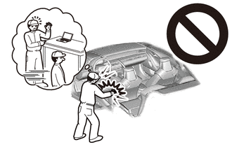
-
Be sure to read Precaution thoroughly before servicing.
- ·
- NOTICE:
-
After turning the ignition switch off, waiting time may be required before disconnecting the cable from the auxiliary negative (-) battery terminal.
2.PLACE FRONT WHEELS FACING STRAIGHT AHEAD
3.DISCONNECT CABLE FROM NEGATIVE AUXILIARY BATTERY TERMINAL
- CAUTION:
-
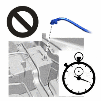
- ·
Wait at least 60 seconds after disconnecting the cable from the negative (-) auxiliary battery terminal to disable the SRS system.
·If the airbag deploys for any reason, it may cause a serious accident.
for M20C-FKS:
Click hereGeneral>MAINTENANCE>M20C-FKS BATTERY>REMOVAL202409,999999,_V1,_083136,_0418197,RM100000002NHPI,
for M20D-FKS:
Click hereGeneral>MAINTENANCE>M20D-FKS BATTERY>REMOVAL202409,999999,_V1,_083136,_0403617,RM100000002NHPJ,
45100
4.REMOVE STEERING WHEEL ASSEMBLY
5.INSPECT SPIRAL CABLE SUB-ASSEMBLY
Check that the front wheels are facing straight ahead.
Check that the spiral cable sub-assembly is in the center position.
- OK:
The connector is at the top.
The colored roller or the top of the flat cable U-turn can be checked from the check window.
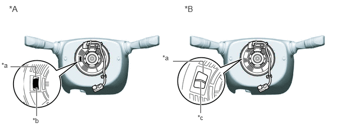
| *A | Colored Roller (Visible Type) | *B | Flat Cable (Visible Type) |
| *a | Check Window | *b | Colored Roller |
| *c | Top of Flat Cable U-turn | - | - |
- NOTICE:
-
If the result is not as specified, it is possible that the spiral cable sub-assembly is broken. Replace the spiral cable sub-assembly with a new one.
45287
6.REMOVE LOWER STEERING COLUMN COVER
45286B
7.REMOVE UPPER STEERING COLUMN COVER
8.REMOVE SPIRAL CABLE WITH SENSOR SUB-ASSEMBLY
- NOTICE:
- ·
Do not replace the spiral cable with sensor sub-assembly with the auxiliary battery connected and the ignition switch ON.
·Do not rotate the spiral cable with sensor sub-assembly with the auxiliary battery connected and the ignition switch ON.
·When rotating the spiral cable with sensor sub-assembly to check the operation of the spiral cable with sensor sub-assembly (checking for abnormal noise, checking the Data List, etc.), make sure to perform the inspection with the steering wheel assembly installed.
Disconnect each connector.
- NOTICE:
-
When disconnecting any airbag connector, take care not to damage the airbag wire harness.
- HINT:
-
Refer to How to Connect or Disconnect Airbag Connector:
- ·
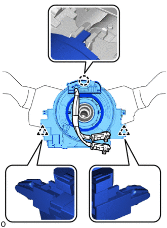
Detach the claw and clip to remove the spiral cable with sensor sub-assembly.
9.REMOVE STEERING SENSOR
- NOTICE:
- ·
Remove the steering sensor from the spiral cable sub-assembly only when replacing the spiral cable sub-assembly.
·Removing the steering sensor from the spiral cable sub-assembly without using a lock pin may result in a misaligned center position of the steering sensor. Therefore, make sure to use the lock pin provided with a new spiral cable sub-assembly when removing the steering sensor from the spiral cable sub-assembly.
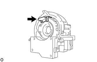
Install the lock pin to the steering sensor.
- NOTICE:
- ·
Use the lock pin provided with a new spiral cable sub-assembly.
·Do not remove the lock pin before the spiral cable sub-assembly is installed to the steering sensor.
Remove the steering sensor.