DOOR / HATCH POWER BACK DOOR SYSTEM Power Back Door does not Operate Using Outside Switch
DESCRIPTION
The No. 1 power back door control switch signal is sent to the multiplex network door ECU.
If the power back door does not operate using the No. 1 power back door control switch, a No. 1 power back door control switch circuit malfunction is a possible cause.
WIRING DIAGRAM
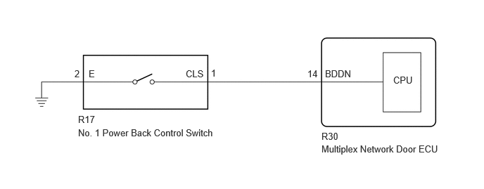
CAUTION / NOTICE / HINT
- NOTICE:
-
If the multiplex network door ECU has been replaced, or if any of the connectors has been disconnected, initialize the power back door system.
PROCEDURE
Operate the multi-information display and check the customization status.
| Display | Description | Default | Setting | Relevant ECU |
|---|---|---|---|---|
| System Settings | Function that enables or disables the power back door operation. | On | On or Off | Multiplex network door ECU |
- Result:
Result Proceed to Customization item is "On" (power back door system operation is possible) A Customization item is "Off" (power back door system operation is prohibited) B
A
B
Check the power back door system.
- Result:
Result Proceed to Power back door system operates normally A Power back door system does not operate normally B
A
B
Read the Data List according to the display on the GTS.
- Body Electrical > Back Door > Data List
-
Tester Display Measurement Item Range Normal Condition Diagnostic Note PBD Close Switch Power back door control switch signal ON or OFF ON: No. 1 power back door control switch pushed
OFF: No. 1 power back door control switch not pushed-
- Body Electrical > Back Door > Data List
-
Tester Display PBD Close Switch - 50003 489 1038
- OK:
The GTS display changes correctly in response to the switch operation.
- Result:
Proceed to OK NG
OK
NG
- Result:
Proceed to OK NG
OK
NG
Disconnect the R17 No. 1 power back door control switch connector.
Disconnect the R30 multiplex network door ECU connector.
Measure the resistance according to the value(s) in the table below.
- Standard Resistance:
Tester Connection Condition Specified Condition R17-1 (CLS) - R30-14 (BDDN) Always Below 1 Ω R17-2 (E) - Body ground Always Below 1 Ω R17-1 (CLS) or R30-14 (BDDN) - Body ground Always 10 kΩ or higher
- Result:
Proceed to OK NG
OK
NG