BRAKE CONTROL / DYNAMIC CONTROL SYSTEMS ELECTRONICALLY CONTROLLED BRAKE SYSTEM(for Gasoline Model (NR Series)) C14D71C Multi-axis Acceleration Sensor Module "A" Supply Voltage Circuit Voltage Out of Range
DESCRIPTION
The airbag sensor with ECU assembly has a built-in yaw rate and acceleration sensor and detects the vehicle condition.
This DTC is stored when the skid control ECU (brake actuator assembly) receives a sensor supply voltage malfunction signal from the yaw rate and acceleration sensor (airbag sensor with ECU assembly).
| DTC No. | Detection Item | DTC Detection Condition | Trouble Area |
|---|---|---|---|
| C14D71C | Multi-axis Acceleration Sensor Module "A" Supply Voltage Circuit Voltage Out of Range | Vehicle speed is 6 km/h (4 mph) or more and yaw rate and acceleration sensor power supply malfunction signal is received for 1 second or more. | ·
Wire harness or connector ·
Yaw rate sensor (airbag sensor with ECU assembly) |
WIRING DIAGRAM
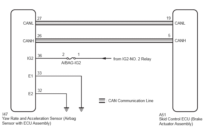
CAUTION / NOTICE / HINT
- NOTICE:
- ·
Inspect the fuses for circuits related to this system before performing the following procedure.
·After replacing or reinstalling the yaw rate and acceleration sensor (airbag sensor with ECU assembly), perform acceleration sensor zero point calibration and store system information memorization after performing "Reset Memory".
·When removing/installing a supplemental restraint systems related component, disconnect the cable from the negative (-) battery terminal before performing the procedure.
PROCEDURE
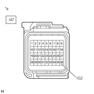
| *a | Front view of wire harness connector
(to Yaw Rate and Acceleration Sensor (Airbag Sensor with ECU Assembly)) |
Turn the ignition switch off.
Disconnect the cable from the negative (-) battery terminal.
- CAUTION:
-
Wait at least 90 seconds after disconnecting the cable from the negative (-) battery terminal to disable the SRS system.
Make sure that there is no looseness at the locking part and the connecting part of the connector.
- OK:
The connector is securely connected.
Disconnect the I47 yaw rate and acceleration sensor (airbag sensor with ECU assembly) connector.
Check both the connector case and the terminals for deformation and corrosion.
- OK:
No deformation or corrosion.
Connect the cable to the negative (-) battery terminal.
Turn the ignition switch to ON.
Operate all the components of the electrical system (defogger, wipers, headlights, heater blower, etc.).
Measure the voltage according to the value(s) in the table below.
- Standard Voltage:
Tester Connection Condition Specified Condition I47-36 (IG2) - Body ground Ignition switch ON 8 to 16 V
- Result:
Proceed to OK NG
OK
NG
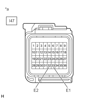
| *a | Front view of wire harness connector
(to Yaw Rate and Acceleration Sensor (Airbag Sensor with ECU Assembly)) |
Turn the ignition switch off.
Disconnect the cable from the negative (-) battery terminal.
- CAUTION:
-
Wait at least 90 seconds after disconnecting the cable from the negative (-) battery terminal to disable the SRS system.
Make sure that there is no looseness at the locking part and the connecting part of the connector.
- OK:
The connector is securely connected.
Disconnect the I47 yaw rate and acceleration sensor (airbag sensor with ECU assembly) connector.
Check both the connector case and the terminals for deformation and corrosion.
- OK:
No deformation or corrosion.
Measure the resistance according to the value(s) in the table below.
- Standard Resistance:
Tester Connection Condition Specified Condition I47-33 (E1) - Body ground 1 minute or more after disconnecting the cable from the negative (-) battery terminal Below 1 Ω I47-32 (E2) - Body ground 1 minute or more after disconnecting the cable from the negative (-) battery terminal Below 1 Ω
- Result:
Proceed to OK NG
OK
NG