METER / GAUGE / DISPLAY METER / GAUGE SYSTEM(for 12.3 Inch Display) TERMINALS OF ECU
COMBINATION METER ASSEMBLY
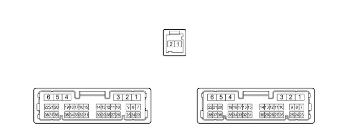
Measure the voltage and resistance and check for pulses according to the value(s) in the table below.
| Terminal No. (Symbol) | Terminal Description | Condition | Specified Condition |
|---|---|---|---|
| I4-1 (EP) - Body ground | Ground | Always | Below 1 Ω |
| I4-2 (ES) - Body ground | Ground | Always | Below 1 Ω |
| I4-5 (B) - Body ground | Power source for auxiliary battery | ·
Ignition switch off*1 ·
Always*2 |
11 to 14 V |
| I4-6 (IG+) - Body ground | Power source for IG relay | IG OFF → IG ON | ·
Below 1 V → 11 to 14 V*1 ·
Below 1 V → 10.5 to 16 V*2 |
| I4-8 (+S) - Body ground | Vehicle speed output signal | Ignition switch ON, wheel being rotated | Pulse generation
(See waveform 1) |
| I4-9 (S) - Body ground*6 | Engine oil pressure signal | Engine started → not started | 11 to 14 V → Below 1 V |
| I4-11 (SW) - Body ground*7 | Brake fluid level warning switch signal | Ignition switch ON, brake fluid level not low (brake warning light/red (malfunction) off) → low (brake warning light/red (malfunction) on) | 11 to 14 V → Below 1 V |
| I4-12 (HZSW) - Body ground | Hazard warning signal switch signal | Hazard warning signal switch off → on | 11 to 14 V → Below 1 V |
| I4-14 (OILW) - Body ground*3 | Engine oil level sensor signal | Ignition switch ON, engine oil level not low → low | Below 1 V → 11 to 14 V |
| I4-25 (SI) - Body ground | Vehicle speed input signal | Ignition switch ON, wheel being rotated | Pulse generation
(See waveform 1) |
| I4-27 (VCM) - Body ground*2 | Vacuum warning switch signal | Engine started, vacuum warning switch off (brake warning light off) → on (brake warning light on) | 11 to 14 V → Below 1 V |
| I4-28 (LST1) - Body ground*1 | Fuel lid status signal | The following message (interrupt display) being displayed on the multi-information display:
Ready to Refuel |
Pulse generation (See waveform 4) |
| The following message (interrupt display) being displayed on the multi-information display:
Close Fuel Lid |
Pulse generation (See waveform 5) | ||
| I4-29 (BKL) - Body ground | Front driver seat belt buckle switch signal | Ignition switch ON, front driver seat belt unfastened → fastened | 11 to 14 V → Below 1 V |
| I5-2 (B) - Body ground | Power source for auxiliary battery | ·
Ignition switch off*1 ·
Always*2 |
11 to 14 V |
| I5-5 (LL) - Body ground | Front/side turn signal flasher signal
(LH side) |
Turn indicator light (LH) blinking | 11 to 14 V ←→ Below 1 V |
| Turn indicator light (LH) off | Below 1 V | ||
| I5-6 (LR) - Body ground | Front/side turn signal flasher signal
(RH side) |
Turn indicator light (RH) blinking | 11 to 14 V ←→ Below 1 V |
| Turn indicator light (RH) off | Below 1 V | ||
| I5-7 (FR) - I5-25 (FE&B) | Fuel level signal | Ignition switch ON, fuel receiver gauge indicates F → E (fuel level warning light on) | Pulse generation
(See waveform 2) |
| I5-12 (MSTI) - Body ground | Steering pad switch without touch detection function signal | Ignition switch ON, up, down, left and right switches on steering pad switch not pushed | 4.8 to 5.2 V |
| I5-13 (ODO) - Body ground | ODO/TRIP switch signal | Ignition switch ON, ODO/TRIP switch not pushed | 4.8 to 5.2 V |
| I5-14 (CANL) | CAN communication signal | - | - |
| I5-15 (TX-)*4 | Local bus communication signal | - | - |
| I5-21 (TRNR) - Body ground | Rear turn signal flasher signal
(RH side) |
Turn indicator light (RH) blinking | 11 to 14 V ←→ Below 1 V |
| Turn indicator light (RH) off | Below 1 V | ||
| I5-22 (TRNL) - Body ground | Rear turn signal flasher signal
(LH side) |
Turn indicator light (LH) blinking | 11 to 14 V ←→ Below 1 V |
| Turn indicator light (LH) off | Below 1 V | ||
| I5-23 (FV) - Body ground | Power source for fuel sender gauge | Ignition switch ON | Pulse generation
(See waveform 3) |
| I5-25 (FE&B) - Body ground | Ground for fuel sender gauge | Always | Below 1 Ω |
| I5-26 (SW3) - Body ground | Ground for trip switch | Always | Below 1 Ω |
| I5-29 (MSM+) - Body ground | Steering pad switch without touch detection function signal | Ignition switch ON, OK and back switches on steering pad switch not pushed | 4.8 to 5.2 V |
| I5-31 (CANH) | CAN communication signal | - | - |
| I5-32 (TX+)*4 | Local bus communication signal | - | - |
| I215-1 (ET+)*5 | Ethernet communication signal | - | - |
| I215-2 (ET-)*5 | Ethernet communication signal | - | - |
*1: for HV Model
*2: for Gasoline Model
*3: for 8ZR-FXE, M15C-FKS, M15B-FKS
*4: for M20C-FKS
*5: w/ Navigation System
*6: for 8ZR-FXE
*7: except M20F-FXS
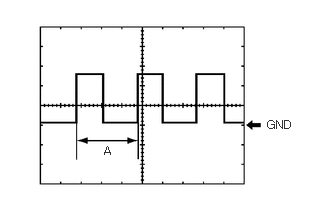
| Item | Condition |
|---|---|
| Tester connection | ·
I4-8 (+S) - Body ground ·
I4-25 (SI) - Body ground |
| Tool setting | 5 V/DIV., 20 ms./DIV. |
| Condition | Ignition switch ON, wheel being rotated |
- HINT:
-
When the system is functioning normally, one wheel revolution generates 4 pulses. As the vehicle speed increases, the width indicated by (A) in the illustration narrows.
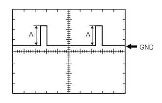
| Item | Condition |
|---|---|
| Tester connection | I5-7 (FR) - I5-25 (FE&B) |
| Tool setting | 2.5 V/DIV., 20 ms./DIV. |
| Condition | Ignition switch ON, fuel receiver gauge indicates F → E (fuel level warning light on) |
- HINT:
-
(A) varies depending on the fuel level.
- for HV Model·
Fuel level full: 4.1 to 4.6 V
·Fuel level low (fuel level warning light on): 0.3 to 0.9 V
- for Gasoline Model (for M15B-FKS, M15C-FKS)·
Fuel level full: 4.1 to 4.6 V
·Fuel level low (fuel level warning light on): 0.3 to 1.0 V
- for Gasoline Model (for M20A-FKS, M20C-FKS, M20E-FKS)·
Fuel level full: 4.1 to 4.6 V
·Fuel level low (fuel level warning light on): 0.3 to 1.0 V

| Item | Condition |
|---|---|
| Tester connection | I5-23 (FV) - Body ground |
| Tool setting | 2.5 V/DIV., 20 ms./DIV. |
| Condition | Ignition switch ON |
| Specified Condition | 4.5 to 5.5 V |
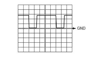
| Item | Condition |
|---|---|
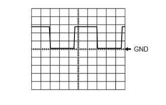
| Tester Connection | I4-28 (LST1) - Body ground |
| Tool setting | 5 V/DIV., 20 ms./DIV. |
| Condition | The following message (interrupt display) being displayed on the multi-information display:
Ready to Refuel |
| Item | Condition |
|---|---|
| Tester Connection | I4-28 (LST1) - Body ground |
| Tool setting | 5 V/DIV., 20 ms./DIV. |
| Condition | The following message (interrupt display) being displayed on the multi-information display:
Close Fuel Lid |
- HINT:
-
This waveform is output when the fuel lid opener switch is operated if the fuel lid is open and any of the following conditions are met:
- ·
The vehicle has been driven for 1 km (0.6 mile) or more at a speed of 50 km/h (31 mph) or more.
·30 minutes or more have elapsed since the fuel lid opener switch was operated.