THEFT DETERRENT / KEYLESS ENTRY IMMOBILISER SYSTEM(w/o Smart Entry and Start System) Security Indicator Light Does not Blink
DESCRIPTION
The transponder key ECU assembly blinks the security indicator light when the immobiliser is set (no key is in the ignition key cylinder).
WIRING DIAGRAM
w/ Security Indicator on Air Conditioning Control Assembly
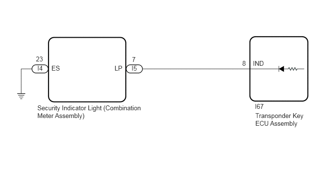
w/ Security Indicator on Combination Meter Assembly
CAUTION / NOTICE / HINT
- NOTICE:
-
Before replacing the transponder key ECU assembly, refer to Service Bulletin.
PROCEDURE
Connect the GTS to the DLC3.
Turn the ignition switch to ON (IG).
Turn the GTS on.
Enter the following menus: Body Electrical / Immobiliser / Active Test.
Perform the Active Test according to the display on the GTS.
- Body Electrical > Immobiliser > Active Test
-
Tester Display Measurement Item Control Range Diagnostic Note Security Indicator Security indicator light ON/OFF -
- Body Electrical > Immobiliser > Active Test
-
Tester Display Security Indicator - 50004 260 1
- OK:
Security indicator light can be turned on and off using the GTS.
- Result:
Proceed to OK NG
OK
NG
Disconnect the I37 security indicator light (air conditioning control assembly) connector.*1
Disconnect the I5 security indicator light (combination meter assembly) connector.*2
*1: w/ Security Indicator on Air Conditioning Control Assembly
*2: w/ Security Indicator on Combination Meter Assembly
Disconnect the I67 transponder key ECU assembly connector.
Measure the resistance according to the value(s) in the table below.
- Standard Resistance:
w/ Security Indicator on Air Conditioning Control Assembly: Tester Connection Condition Specified Condition I85-7 (IND) - I37-10 (LP) Always Below 1 Ω I85-7 (IND) or I37-10 (LP) - Other terminals and body ground Always 10 kΩ or higher
w/ Security Indicator on Combination Meter Assembly: Tester Connection Condition Specified Condition I85-7 (IND) - I5-7 (LP) Always Below 1 Ω I85-7 (IND) or I5-7 (LP) - Other terminals and body ground Always 10 kΩ or higher
- Result:
Proceed to OK NG
OK
NG
Disconnect the I4 security indicator light connector.*
*: w/ Security Indicator on Combination Meter Assembly
Measure the resistance according to the value(s) in the table below.
- Standard Resistance:
w/ Security Indicator on Air Conditioning Control Assembly: Tester Connection Condition Specified Condition I37-13 (ES) - Body ground Always Below 1 Ω
w/ Security Indicator on Combination Meter Assembly: Tester Connection Condition Specified Condition I4-23 (ES) - Body ground Always Below 1 Ω
- Result:
Proceed to OK NG
OK
NG
Connect the I67 transponder key ECU assembly connector.
Connect the I37 security indicator light (air conditioning control assembly) connector.*1
Connect the I4 and I5 security indicator light (combination meter assembly) connectors.*2
*1: w/ Security Indicator on Air Conditioning Control Assembly
*2: w/ Security Indicator on Combination Meter Assembly
Measure the voltage according to the value(s) in the table below.
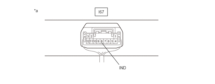
| *a | Component with harness connected
(Transponder Key ECU Assembly) |
- | - |
- Standard Voltage:
Tester Connection Condition Specified Condition I67-8 (IND) - Body ground No door control transmitter assembly in ignition key cylinder, or 20 sec. elapsed after turning ignition switch to ACC or off (immobiliser system set) Pulse generation Door control transmitter assembly in ignition key cylinder (immobiliser system unset) Below 1 V
- Result:
Result Proceed to OK (w/ Security Indicator on Air Conditioning Control Assembly) A OK (w/ Security Indicator on Combination Meter Assembly) B NG C
A
B
C