AUDIO / VIDEO ROOF ANTENNA REMOVAL
CAUTION / NOTICE / HINT
The necessary procedures (adjustment, calibration, initialization or registration) that must be performed after parts are removed and installed, or replaced during telephone antenna assembly removal/installation are shown below.
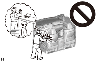
- CAUTION:
-
-
Be sure to read Precaution thoroughly before servicing.
-
except NR Series Engine:
-
for NR Series Engine:
- NOTICE:
-
After the ignition switch is turned off, there may be a waiting time before disconnecting the negative (-) auxiliary battery terminal.
- HINT:
-
When the cable is disconnected / reconnected to the auxiliary battery terminal, systems temporarily stop operating. However, each system has a function that completes learning the first time the system is used.
- ·
for Gasoline Model:
Learning completes when vehicle is driven Effect/Inoperative Function When Necessary Procedures are not Performed Necessary Procedures Link Stop and Start System Idle the engine for approximately 5 to 60 minutes or drive the vehicle until stop and start control is permitted (  201906,999999,_51,_080774,_0393362,RM100000001HXHC,)
Pre-collision System Perform steering sensor zero point calibration ( 202304,999999,_95,_139716,_0601175,RM100000002BFOE,)
Lane Tracing Assist System Front Camera System Drive the vehicle straight ahead at 15 km/h (9 mph) or more for 1 second or more. ( 202304,999999,_95,_139716,_0584193,RM1000000029F4C,)
·for HV Model:
Learning completes when vehicle is driven Effect/Inoperative Function When Necessary Procedures are not Performed Necessary Procedures Link Front Camera System Drive the vehicle straight ahead at 15 km/h (9 mph) or more for 1 second or more. ( 202304,999999,_95,_139716,_0584193,RM1000000029F4C,)
PROCEDURE

 1.REMOVE ROOF HEADLINING ASSEMBLY
2.REMOVE TELEPHONE ANTENNA ASSEMBLY WITH COVER
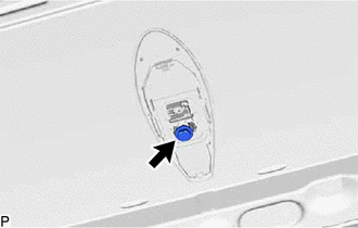
Remove the bolt.
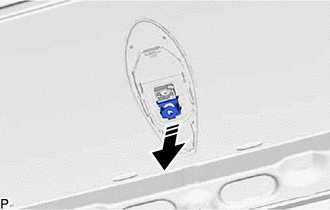

|
Remove in this Direction |
Remove the washer and holder as shown in the illustration.
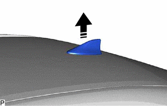
|
|
Remove in this Direction |
Remove the telephone antenna assembly with cover as shown in the illustration.
86760A
3.REMOVE TELEPHONE ANTENNA ASSEMBLY

|
|
Remove in this Direction (1) |

|
Remove in this Direction (2) |
Disengage the 3 claws and 3 guides to remove the telephone antenna assembly as shown in the illustration.
When reusing the telephone antenna assembly:
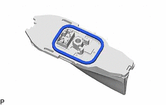
Remove the seal.