REAR SUSPENSION REAR SUSPENSION MEMBER INSTALLATION
PROCEDURE

 1.INSTALL HOLE PLUG (w/ Hole Plug)
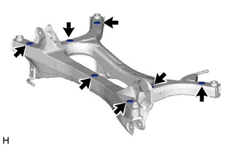
Install the 7 hole plugs to the rear suspension member sub-assembly as shown in the illustration.
51284
2.INSTALL REAR SUSPENSION MEMBER HOLE COVER (w/ Rear Suspension Member Hole Cover)
Install the 4 rear suspension member hole covers to the rear suspension member sub-assembly.
48790
3.INSTALL REAR UPPER CONTROL ARM ASSEMBLY LH
48770A
4.INSTALL REAR UPPER CONTROL ARM ASSEMBLY RH
- HINT:
-
Perform the same procedure as for the LH side.
51206A
5.INSTALL REAR SUSPENSION MEMBER SUB-ASSEMBLY
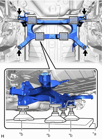
| *a | Engine Lifter |
| *b | Attachment |

|
Attachment Placement Location |
Using an engine lifter and 4 attachments or equivalent tools, support the rear suspension member sub-assembly as shown in the illustration.
- CAUTION:
-
- ·
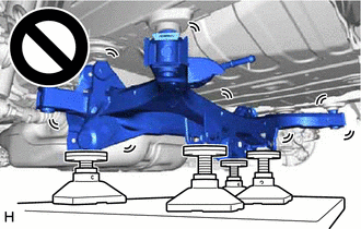
The rear suspension member sub-assembly is a very heavy component. Make sure that it is supported securely.
·If the rear suspension member sub-assembly is not securely supported, it may drop, resulting in serious injury.
- NOTICE:
- ·
Use attachments and wooden blocks to keep the rear suspension member sub-assembly level.
·Keep supporting the rear suspension member sub-assembly until the installation has been completed.
Raise the rear suspension member sub-assembly until there is no clearance between the rear suspension member sub-assembly and vehicle.
Install the rear suspension member sub-assembly with the 2 bolts and 2 nuts.
- Torque:
- 143 N*m (1458 kgf*cm, 105 ft.*lbf)
48790
6.TEMPORARILY INSTALL REAR UPPER CONTROL ARM ASSEMBLY LH
Temporarily install the rear upper control arm assembly LH to the rear axle carrier sub-assembly LH with the bolt and nut.
- NOTICE:
- ·
Insert the bolt with the threaded end facing the rear of the vehicle.
·Because the nut has its own stopper, do not turn the nut. Tighten the bolt with the nut secured.
48770A
7.TEMPORARILY INSTALL REAR UPPER CONTROL ARM ASSEMBLY RH
- HINT:
-
Perform the same procedure as for the LH side.
48720A
8.TEMPORARILY INSTALL REAR NO. 1 SUSPENSION ARM ASSEMBLY LH
48710A
9.TEMPORARILY INSTALL REAR NO. 1 SUSPENSION ARM ASSEMBLY RH
- HINT:
-
Perform the same procedure as for the LH side.
48740F
10.TEMPORARILY INSTALL REAR NO. 2 SUSPENSION ARM ASSEMBLY LH
48730F
11.TEMPORARILY INSTALL REAR NO. 2 SUSPENSION ARM ASSEMBLY RH
- HINT:
-
Perform the same procedure as for the LH side.
48258C
12.INSTALL REAR LOWER COIL SPRING INSULATOR LH
48258B
13.INSTALL REAR LOWER COIL SPRING INSULATOR RH
- HINT:
-
Perform the same procedure as for the LH side.
48231B
14.INSTALL REAR COIL SPRING LH
48231A
15.INSTALL REAR COIL SPRING RH
- HINT:
-
Perform the same procedure as for the LH side.
48805
16.INSTALL REAR STABILIZER BAR SUB-ASSEMBLY (w/ Stabilizer Bar)
47319F
17.INSTALL REAR FLEXIBLE HOSE LH
Install the rear flexible hose LH to the rear flexible hose bracket with the bolt.
- Torque:
- 29 N*m (296 kgf*cm, 21 ft.*lbf)
47318F
18.INSTALL REAR FLEXIBLE HOSE RH
- HINT:
-
Perform the same procedure as for the LH side.
19.STABILIZE SUSPENSION
48840A
20.INSTALL REAR STABILIZER LINK ASSEMBLY LH (w/ Stabilizer Bar)
48830D
21.INSTALL REAR STABILIZER LINK ASSEMBLY RH (w/ Stabilizer Bar)
- HINT:
-
Perform the same procedure as for the LH side.
48720A
22.INSTALL REAR NO. 1 SUSPENSION ARM ASSEMBLY LH
48710A
23.INSTALL REAR NO. 1 SUSPENSION ARM ASSEMBLY RH
- HINT:
-
Perform the same procedure as for the LH side.
48740F
24.INSTALL REAR NO. 2 SUSPENSION ARM ASSEMBLY LH
Install the rear No. 2 suspension arm assembly LH (rear axle carrier sub-assembly side) with the bolt.
48730F
25.INSTALL REAR NO. 2 SUSPENSION ARM ASSEMBLY RH
- HINT:
-
Perform the same procedure as for the LH side.
48790
26.INSTALL REAR UPPER CONTROL ARM ASSEMBLY LH
Install the rear upper control arm assembly LH to the rear axle carrier sub-assembly LH with the bolt.
- Torque:
- 73 N*m (744 kgf*cm, 54 ft.*lbf)
- NOTICE:
-
Because the nut has its own stopper, do not turn the nut. Tighten the bolt with the nut secured.
48770A
27.INSTALL REAR UPPER CONTROL ARM ASSEMBLY RH
- HINT:
-
Perform the same procedure as for the LH side.
57628E
28.INSTALL REAR FLOOR SIDE MEMBER COVER LH (for HV Model)
57627G
29.INSTALL REAR FLOOR SIDE MEMBER COVER RH (for HV Model)
57628E
30.INSTALL REAR FLOOR SIDE MEMBER COVER LH (for Gasoline Model)
57627G
31.INSTALL REAR FLOOR SIDE MEMBER COVER RH (for Gasoline Model)
17430
32.INSTALL TAIL EXHAUST PIPE ASSEMBLY
for M15B-FKS: Click hereEngine / Hybrid System>M15B-FKS (INTAKE / EXHAUST)>EXHAUST PIPE>INSTALLATION202101,999999,_51,_096204,_0455168,RM100000001TIBA_02_0028,
for M15C-FKS: Click hereEngine / Hybrid System>M15C-FKS (INTAKE / EXHAUST)>EXHAUST PIPE>INSTALLATION202101,999999,_51,_096209,_0455173,RM100000001TIBN_02_0028,
for M20A-FKS: Click hereEngine / Hybrid System>M20A-FKS (INTAKE / EXHAUST)>EXHAUST PIPE>INSTALLATION202104,999999,_51,_101148,_0473516,RM100000001W2ON_02_0028,
for M20C-FKS: Click hereEngine / Hybrid System>M20C-FKS (INTAKE / EXHAUST)>EXHAUST PIPE>INSTALLATION202107,999999,_51,_105198,_0483680,RM100000001X8JC_02_0028,
for M20E-FKS: Click hereEngine / Hybrid System>M20E-FKS (INTAKE / EXHAUST)>EXHAUST PIPE>INSTALLATION202104,999999,_51,_101158,_0477648,RM100000001WH7L_02_0028,
for 8ZR-FXE: Click hereEngine / Hybrid System>8ZR-FXE (INTAKE / EXHAUST)>EXHAUST PIPE>INSTALLATION202304,999999,_51,_080790,_0392074,RM100000002B0R0_01_0024,
for NR Series: Click hereEngine / Hybrid System>NR Series (INTAKE / EXHAUST)>EXHAUST PIPE>INSTALLATION201906,999999,_51,_080791,_0392520,RM100000001HREN_01_0024,
for M20F-FXS, M20G-FXS: Click hereEngine / Hybrid System>M20F-FXS, M20G-FXS (INTAKE / EXHAUST)>EXHAUST PIPE>INSTALLATION202307,999999,_51,_146898,_0614250,RM100000002CQYO_02_0028,
33.INSTALL REAR WHEEL
48740F
34.INSTALL REAR NO. 2 SUSPENSION ARM ASSEMBLY LH
Install the rear No. 2 suspension arm assembly LH (rear suspension member sub-assembly side) with the nut.
48730F
35.INSTALL REAR NO. 2 SUSPENSION ARM ASSEMBLY RH
- HINT:
-
Perform the same procedure as for the LH side.
36.INSPECT FOR EXHAUST GAS LEAK
for M15B-FKS: Click hereEngine / Hybrid System>M15B-FKS (INTAKE / EXHAUST)>EXHAUST PIPE>INSTALLATION202101,999999,_51,_096204,_0455168,RM100000001TIBA_02_0013,
for M15C-FKS: Click hereEngine / Hybrid System>M15C-FKS (INTAKE / EXHAUST)>EXHAUST PIPE>INSTALLATION202101,999999,_51,_096209,_0455173,RM100000001TIBN_02_0013,
for M20A-FKS: Click hereEngine / Hybrid System>M20A-FKS (INTAKE / EXHAUST)>EXHAUST PIPE>INSTALLATION202104,999999,_51,_101148,_0473516,RM100000001W2ON_02_0013,
for M20C-FKS: Click hereEngine / Hybrid System>M20C-FKS (INTAKE / EXHAUST)>EXHAUST PIPE>INSTALLATION202107,999999,_51,_105198,_0483680,RM100000001X8JC_02_0013,
for M20E-FKS: Click hereEngine / Hybrid System>M20E-FKS (INTAKE / EXHAUST)>EXHAUST PIPE>INSTALLATION202104,999999,_51,_101158,_0477648,RM100000001WH7L_02_0013,
for 8ZR-FXE: Click hereEngine / Hybrid System>8ZR-FXE (INTAKE / EXHAUST)>EXHAUST PIPE>INSTALLATION202304,999999,_51,_080790,_0392074,RM100000002B0R0_01_0041,
for NR Series: Click hereEngine / Hybrid System>NR Series (INTAKE / EXHAUST)>EXHAUST PIPE>INSTALLATION201906,999999,_51,_080791,_0392520,RM100000001HREN_01_0041,
for M20F-FXS, M20G-FXS: Click hereEngine / Hybrid System>M20F-FXS, M20G-FXS (INTAKE / EXHAUST)>EXHAUST PIPE>INSTALLATION202307,999999,_51,_146898,_0614250,RM100000002CQYO_02_0013,
37.INSPECT AND ADJUST REAR WHEEL ALIGNMENT
38.PERFORM INITIALIZATION
| Parking Assist Monitor System | ( 202304,999999,_56,_080754,_0596561,RM100000002AX0C,) 202304,999999,_56,_080754,_0596561,RM100000002AX0C,)
|
| Panoramic View Monitor System | (202307,999999,_56,_080754,_0612151,RM100000002CL9H,)
|
| Parking Assist Monitor System | (202304,999999,_56,_080754,_0596561,RM100000002AX0C,)
|