REAR SUSPENSION REAR SHOCK ABSORBER(for Double Wishbone Type Suspension) INSTALLATION
CAUTION / NOTICE / HINT
- HINT:
- ·
Use the same procedure for the RH side and LH side.
·The following procedure is for the LH side.
PROCEDURE

 48760B
1.INSTALL REAR SUSPENSION SUPPORT ASSEMBLY
48760B
1.INSTALL REAR SUSPENSION SUPPORT ASSEMBLY
Secure the rear suspension support assembly in a vise using aluminum plates.
- NOTICE:
-
Do not overtighten the vise.
Install the rear suspension support assembly to the rear shock absorber assembly.
Temporarily tighten a new rear support to rear shock absorber nut to the rear shock absorber assembly.
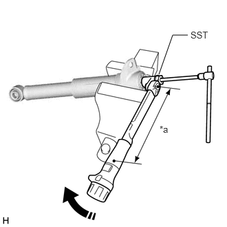
| *a | Torque Wrench Fulcrum Length |
Using SST and a 6 mm hexagon socket wrench, hold the rear shock absorber rod and tighten the rear support to rear shock absorber nut.
- SST
- 09729-97202
- Torque:
- Specified tightening torque : 25 N*m (255 kgf*cm, 18 ft.*lbf)
- NOTICE:
-
Securely insert the 6 mm hexagon socket wrench into the rear shock absorber rod to prevent damage to the rear shock absorber assembly when tightening the rear support to rear shock absorber nut.
- HINT:
- ·
Calculate the torque wrench reading when changing the fulcrum length of the torque wrench.
·When using SST (fulcrum length of 40 mm (1.57 in.)) + torque wrench (fulcrum length of 180 mm (7.09 in.)):
20 N*m (204 kgf*cm, 15 ft.*lbf)
48554A
2.INSTALL REAR SHOCK ABSORBER CAP
Install the rear shock absorber cap to the rear shock absorber assembly.
48540
3.TEMPORARILY INSTALL REAR SHOCK ABSORBER ASSEMBLY
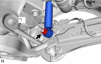
| *1 | Rear Axle Carrier Pin |
Temporarily install the rear shock absorber assembly to the rear axle carrier sub-assembly with the nut and plate washer.
- NOTICE:
-
Hold the rear axle carrier pin while rotating the nut.
4.STABILIZE SUSPENSION
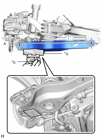
| *a | Wooden Block |
| *b | Jack |

|
Wooden Block Placement Location |
Using a jack and a wooden block, apply load to the suspension so that the rear No. 2 suspension arm assembly is positioned as shown in the illustration.
- Standard Length (A):
13 mm (0.512 in.)
- CAUTION:
-
Do not jack up the rear No. 2 suspension arm assembly too high as the vehicle may fall.
- NOTICE:
- ·
When jacking up the rear No. 2 suspension arm assembly, be sure to jack it up slowly.
·Make sure to perform this operation with the vehicle kept as low as possible.
48790
5.INSTALL REAR UPPER CONTROL ARM ASSEMBLY
Install the rear upper control arm assembly to the rear axle carrier sub-assembly with the bolt and nut.
- Torque:
- 73 N*m (744 kgf*cm, 54 ft.*lbf)
- NOTICE:
- ·
Insert the bolt with the threaded end facing the rear of the vehicle.
·Because the nut has its own stopper, do not turn the nut. Tighten the bolt with the nut secured.
48540
6.CONNECT REAR SHOCK ABSORBER ASSEMBLY
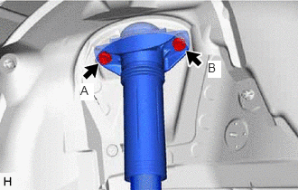
Connect the rear shock absorber assembly to the vehicle with the 2 bolts.
- Torque:
- 55 N*m (561 kgf*cm, 41 ft.*lbf)
- NOTICE:
-
Temporarily tighten the bolt (A) and then fully tighten the 2 bolts in the order of (B) and (A).
48540
7.INSTALL REAR SHOCK ABSORBER ASSEMBLY
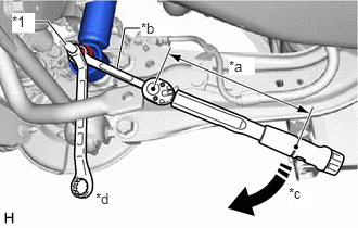
| *1 | Rear Axle Carrier Pin |
| *a | Torque Wrench Fulcrum Length |
| *b | Ball Joint Lock Nut Wrench |
| *c | Turn |
| *d | Hold |
Using a ball joint lock nut wrench fully tighten the rear shock absorber assembly with the nut.
- Torque:
- Specified tightening torque : 125 N*m (1275 kgf*cm, 92 ft.*lbf)
- NOTICE:
-
Hold the rear axle carrier pin while rotating the nut.
- HINT:
- ·
Calculate the torque wrench reading when changing the fulcrum length of the torque wrench.
·When using a ball joint lock nut wrench (fulcrum length of 149.75 mm (5.90 in.)) + torque wrench (fulcrum length of 400 mm (1.31 ft.)):
91 N*m (928 kgf*cm, 67 ft.*lbf)
48840A
8.INSTALL REAR STABILIZER LINK ASSEMBLY (w/ Stabilizer Bar)
57628E
9.INSTALL REAR FLOOR SIDE MEMBER COVER LH (for HV Model)
57627G
10.INSTALL REAR FLOOR SIDE MEMBER COVER RH (for HV Model)
57628E
11.INSTALL REAR FLOOR SIDE MEMBER COVER LH (for Gasoline Model)
57627G
12.INSTALL REAR FLOOR SIDE MEMBER COVER RH (for Gasoline Model)
13.INSTALL REAR WHEEL
14.INSPECT AND ADJUST REAR WHEEL ALIGNMENT
15.PERFORM INITIALIZATION
| Parking Assist Monitor System | ( 202304,999999,_56,_080754,_0596561,RM100000002AX0C,) 202304,999999,_56,_080754,_0596561,RM100000002AX0C,)
|
| Panoramic View Monitor System | (202307,999999,_56,_080754,_0612151,RM100000002CL9H,)
|
| Parking Assist Monitor System | (202304,999999,_56,_080754,_0596561,RM100000002AX0C,)
|