FRONT SUSPENSION FRONT SUSPENSION MEMBER INSTALLATION
PROCEDURE

 51618
1.INSTALL FRONT DIFFERENTIAL SUPPORT GUARD LH (w/ Differential Support Guard)
51618
1.INSTALL FRONT DIFFERENTIAL SUPPORT GUARD LH (w/ Differential Support Guard)
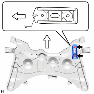
| *a | Arrow |

|
Front of the Vehicle |
Install the front differential support guard LH to the front suspension crossmember sub-assembly with the 2 bolts.
- Torque:
- 18.5 N*m (189 kgf*cm, 14 ft.*lbf)
- NOTICE:
-
Make sure to install the front differential support guard LH with its arrow facing the front of the vehicle.
2.INSTALL HOLE PLUG
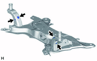
Install the 4 hole plugs to the front suspension crossmember sub-assembly.
- HINT:
-
There are 2 different shapes of hole plug.
51228G
3.INSTALL FRONT SUSPENSION MEMBER PLATE
Install the 2 front suspension member plates to the front suspension crossmember sub-assembly.
48069
4.TEMPORARILY INSTALL FRONT LOWER NO. 1 SUSPENSION ARM SUB-ASSEMBLY LH
Temporarily install the front lower No. 1 suspension arm sub-assembly LH to the front suspension crossmember sub-assembly with the 2 bolts and nut.
48068
5.TEMPORARILY INSTALL FRONT LOWER NO. 1 SUSPENSION ARM SUB-ASSEMBLY RH
Temporarily install the front lower No. 1 suspension arm sub-assembly RH to the front suspension crossmember sub-assembly with the 2 bolts and nut.
for NR Series Engine:
- HINT:
-
As the bolt on the front of the front lower No. 1 suspension arm sub-assembly RH cannot be fully tightened on the vehicle, fully tighten the bolt before the front suspension crossmember sub-assembly is installed to the vehicle.
Position the front suspension crossmember sub-assembly on a level surface.
Position the front lower No. 1 suspension arm sub-assembly RH as shown in the illustration.
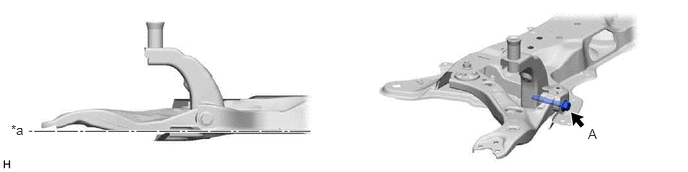
| *a | Horizontal | - | - |
Tighten the bolt (A).
- Torque:
- 240 N*m (2447 kgf*cm, 177 ft.*lbf)
12363A
6.INSTALL ENGINE MOVING CONTROL ROD
Install the engine moving control rod to the front suspension crossmember sub-assembly with the bolt.
- Torque:
- 200 N*m (2039 kgf*cm, 148 ft.*lbf)
48811
7.INSTALL FRONT STABILIZER BAR
48829A
8.INSTALL FRONT NO. 1 STABILIZER BRACKET LH
48824A
9.INSTALL FRONT NO. 1 STABILIZER BRACKET RH
- HINT:
-
Perform the same procedure as for the LH side.
10.INSTALL STEERING LINK ASSEMBLY
51201
11.INSTALL FRONT SUSPENSION CROSSMEMBER SUB-ASSEMBLY
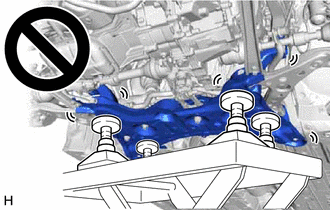
Slowly jack up the front suspension crossmember sub-assembly with an engine lifter using 4 attachments or equivalent tools.
- CAUTION:
-
- ·
The front suspension crossmember sub-assembly is a very heavy component. Make sure that it is supported securely.
·If the front suspension crossmember sub-assembly is not securely supported, it may drop, resulting in serious injury.
- NOTICE:
-
Use attachments to keep the front suspension crossmember sub-assembly level.
Install the front suspension crossmember sub-assembly to the vehicle body with the 4 bolts.
- Torque:
- 141 N*m (1438 kgf*cm, 104 ft.*lbf)
Lower the engine lifter.
Install the engine moving control rod with the bolt.
- Torque:
- 170 N*m (1734 kgf*cm, 125 ft.*lbf)
Install the 2 wire harness clamp brackets to the front suspension crossmember sub-assembly with the 2 bolts.
- Torque:
- 13 N*m (133 kgf*cm, 10 ft.*lbf)
48069
12.CONNECT FRONT LOWER NO. 1 SUSPENSION ARM SUB-ASSEMBLY LH
48068
13.CONNECT FRONT LOWER NO. 1 SUSPENSION ARM SUB-ASSEMBLY RH
- HINT:
-
Perform the same procedure as for the LH side.
45047
14.CONNECT TIE ROD END SUB-ASSEMBLY LH
45046
15.CONNECT TIE ROD END SUB-ASSEMBLY RH
- HINT:
-
Perform the same procedure as for the LH side.
48810
16.CONNECT FRONT STABILIZER LINK ASSEMBLY LH
Connect the front stabilizer link assembly LH to the front stabilizer bar with the nut.
- Torque:
- 74 N*m (755 kgf*cm, 55 ft.*lbf)
- NOTICE:
-
Do not damage the boot of the ball joint.
- HINT:
-
If the ball joint turns together with the nut, use a 6 mm hexagon socket wrench to hold the stud bolt.
48820B
17.CONNECT FRONT STABILIZER LINK ASSEMBLY RH
- HINT:
-
Perform the same procedure as for the LH side.
51108A
18.INSTALL REAR SIDE RAIL REINFORCEMENT SUB-ASSEMBLY LH
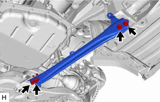
Install the rear side rail reinforcement sub-assembly LH to the front suspension crossmember sub-assembly and vehicle body with the 4 bolts.
- Torque:
- 70 N*m (714 kgf*cm, 52 ft.*lbf)
51107A
19.INSTALL REAR SIDE RAIL REINFORCEMENT SUB-ASSEMBLY RH
- HINT:
-
Perform the same procedure as for the LH side.
45025D
20.CONNECT NO. 1 STEERING COLUMN HOLE COVER SUB-ASSEMBLY
45260
21.CONNECT NO. 2 STEERING INTERMEDIATE SHAFT ASSEMBLY
45259A
22.INSTALL COLUMN HOLE COVER SILENCER SHEET
23.INSTALL FRONT WHEELS
24.STABILIZE SUSPENSION
Lower the vehicle.
Bounce the vehicle up and down several times to stabilize the suspension.
48069
25.FULLY TIGHTEN FRONT LOWER NO. 1 SUSPENSION ARM SUB-ASSEMBLY LH
48068
26.FULLY TIGHTEN FRONT LOWER NO. 1 SUSPENSION ARM SUB-ASSEMBLY RH
51444A
27.INSTALL REAR ENGINE UNDER COVER LH
for M15B-FKS: Click hereEngine / Hybrid System>M15B-FKS (ENGINE MECHANICAL)>ENGINE ASSEMBLY>INSTALLATION202304,999999,_51,_096197,_0454892,RM100000002BBF1_01_0387,
for M15C-FKS: Click hereEngine / Hybrid System>M15C-FKS (ENGINE MECHANICAL)>ENGINE ASSEMBLY>INSTALLATION202304,999999,_51,_096206,_0454902,RM100000002BBQF_01_0387,
for M20A-FKS: Click hereEngine / Hybrid System>M20A-FKS (ENGINE MECHANICAL)>ENGINE ASSEMBLY>INSTALLATION202304,999999,_51,_101145,_0470307,RM100000002BFCZ_01_0387,
for M20C-FKS: Click hereEngine / Hybrid System>M20C-FKS (ENGINE MECHANICAL)>ENGINE ASSEMBLY>INSTALLATION202304,999999,_51,_105191,_0481157,RM100000002BFD2_01_0387,
for M20E-FKS: Click hereEngine / Hybrid System>M20E-FKS (ENGINE MECHANICAL)>ENGINE ASSEMBLY>INSTALLATION202304,999999,_51,_101154,_0476817,RM100000002BFD9_01_0387,
for M20F-FXS, M20G-FXS: Click hereEngine / Hybrid System>M20F-FXS, M20G-FXS (ENGINE MECHANICAL)>ENGINE ASSEMBLY>INSTALLATION202307,999999,_51,_146897,_0611496,RM100000002CJ21_01_0387,
for 8ZR-FXE: Click hereEngine / Hybrid System>8ZR-FXE (ENGINE MECHANICAL)>ENGINE ASSEMBLY>INSTALLATION202304,999999,_51,_080726,_0391619,RM100000002B5Z9_01_0389,
for NR Series Engine: Click hereEngine / Hybrid System>NR Series (ENGINE MECHANICAL)>ENGINE ASSEMBLY>INSTALLATION202304,999999,_51,_080739,_0391935,RM100000002BCNA_01_0448,
51443C
28.INSTALL REAR ENGINE UNDER COVER RH
for M15B-FKS: Click hereEngine / Hybrid System>M15B-FKS (ENGINE MECHANICAL)>ENGINE ASSEMBLY>INSTALLATION202304,999999,_51,_096197,_0454892,RM100000002BBF1_01_0388,
for M15C-FKS: Click hereEngine / Hybrid System>M15C-FKS (ENGINE MECHANICAL)>ENGINE ASSEMBLY>INSTALLATION202304,999999,_51,_096206,_0454902,RM100000002BBQF_01_0388,
for M20A-FKS: Click hereEngine / Hybrid System>M20A-FKS (ENGINE MECHANICAL)>ENGINE ASSEMBLY>INSTALLATION202304,999999,_51,_101145,_0470307,RM100000002BFCZ_01_0388,
for M20C-FKS: Click hereEngine / Hybrid System>M20C-FKS (ENGINE MECHANICAL)>ENGINE ASSEMBLY>INSTALLATION202304,999999,_51,_105191,_0481157,RM100000002BFD2_01_0388,
for M20E-FKS: Click hereEngine / Hybrid System>M20E-FKS (ENGINE MECHANICAL)>ENGINE ASSEMBLY>INSTALLATION202304,999999,_51,_101154,_0476817,RM100000002BFD9_01_0388,
for M20F-FXS, M20G-FXS: Click hereEngine / Hybrid System>M20F-FXS, M20G-FXS (ENGINE MECHANICAL)>ENGINE ASSEMBLY>INSTALLATION202307,999999,_51,_146897,_0611496,RM100000002CJ21_01_0388,
for 8ZR-FXE: Click hereEngine / Hybrid System>8ZR-FXE (ENGINE MECHANICAL)>ENGINE ASSEMBLY>INSTALLATION202304,999999,_51,_080726,_0391619,RM100000002B5Z9_01_0434,
for NR Series Engine: Click hereEngine / Hybrid System>NR Series (ENGINE MECHANICAL)>ENGINE ASSEMBLY>INSTALLATION202304,999999,_51,_080739,_0391935,RM100000002BCNA_01_0451,
51410
29.INSTALL NO. 1 ENGINE UNDER COVER ASSEMBLY
for M15B-FKS: Click hereEngine / Hybrid System>M15B-FKS (ENGINE MECHANICAL)>ENGINE ASSEMBLY>INSTALLATION202304,999999,_51,_096197,_0454892,RM100000002BBF1_01_0389,
for M15C-FKS: Click hereEngine / Hybrid System>M15C-FKS (ENGINE MECHANICAL)>ENGINE ASSEMBLY>INSTALLATION202304,999999,_51,_096206,_0454902,RM100000002BBQF_01_0389,
for M20A-FKS: Click hereEngine / Hybrid System>M20A-FKS (ENGINE MECHANICAL)>ENGINE ASSEMBLY>INSTALLATION202304,999999,_51,_101145,_0470307,RM100000002BFCZ_01_0389,
for M20C-FKS: Click hereEngine / Hybrid System>M20C-FKS (ENGINE MECHANICAL)>ENGINE ASSEMBLY>INSTALLATION202304,999999,_51,_105191,_0481157,RM100000002BFD2_01_0389,
for M20E-FKS: Click hereEngine / Hybrid System>M20E-FKS (ENGINE MECHANICAL)>ENGINE ASSEMBLY>INSTALLATION202304,999999,_51,_101154,_0476817,RM100000002BFD9_01_0389,
for M20F-FXS, M20G-FXS: Click hereEngine / Hybrid System>M20F-FXS, M20G-FXS (ENGINE MECHANICAL)>ENGINE ASSEMBLY>INSTALLATION202307,999999,_51,_146897,_0611496,RM100000002CJ21_01_0389,
for 8ZR-FXE: Click hereEngine / Hybrid System>8ZR-FXE (ENGINE MECHANICAL)>ENGINE ASSEMBLY>INSTALLATION202304,999999,_51,_080726,_0391619,RM100000002B5Z9_01_0392,
for NR Series Engine: Click hereEngine / Hybrid System>NR Series (ENGINE MECHANICAL)>ENGINE ASSEMBLY>INSTALLATION202304,999999,_51,_080739,_0391935,RM100000002BCNA_01_0452,
30.INSPECT AND ADJUST FRONT WHEEL ALIGNMENT
31.PERFORM INITIALIZATION
| Parking Assist Monitor System | ( 202304,999999,_56,_080754,_0596561,RM100000002AX0C,) 202304,999999,_56,_080754,_0596561,RM100000002AX0C,)
|
| Panoramic View Monitor System | (202307,999999,_56,_080754,_0612151,RM100000002CL9H,)
|
| Parking Assist Monitor System | (202304,999999,_56,_080754,_0596561,RM100000002AX0C,)
|