ACOUSTIC VEHICLE ALERTING SYSTEM ACOUSTIC VEHICLE ALERTING SYSTEM B135013 Acoustic Vehicle Alerting Speaker Circuit Open B135019 Acoustic Vehicle Alerting Speaker Circuit Current Above Threshold
DESCRIPTION
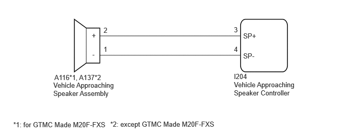
The vehicle approaching speaker assembly circuit consists of the vehicle approaching speaker controller and vehicle approaching speaker assembly.
This DTC is stored when a malfunction is detected in the vehicle approaching speaker assembly circuit or vehicle approaching speaker controller.
| DTC No. | Detection Item | DTC Detection Condition | Trouble Area |
|---|---|---|---|
| B135013 | Acoustic Vehicle Alerting Speaker Circuit Open | Detection condition:
1.
The ignition switch is ON. 2.
Power source voltage is 10 V or more. Malfunction status:
When ECU output sound signal is being monitored with warning sound not being output, a speaker circuit open, short or short to ground is detected. Malfunction duration:
5 seconds or more |
·
Vehicle approaching speaker controller ·
Vehicle approaching speaker assembly ·
Harness or connector |
| B135019 | Acoustic Vehicle Alerting Speaker Circuit Current Above Threshold | Detection condition:
1.
The ignition switch is ON. 2.
Power source voltage is 9 V or more. Malfunction status:
When vehicle proximity warning sound output conditions are met, an internal malfunction is continuously detected in the vehicle approaching speaker controller. Malfunction duration:
1 second or more |
·
Vehicle approaching speaker controller ·
Vehicle approaching speaker assembly ·
Harness or connector |
WIRING DIAGRAM
PROCEDURE
- Result:
Proceed to OK NG
OK
NG
Disconnect the I204 vehicle approaching speaker controller connector.
for GTMC Made M20F-FXS:
Disconnect the A116 vehicle approaching speaker assembly connector.
except GTMC Made M20F-FXS:
Disconnect the A137 vehicle approaching speaker assembly connector.
Measure the resistance according to the value(s) in the table below.
- Standard Resistance (for GTMC Made M20F-FXS):
Tester Connection Condition Specified Condition A116-2 (+) - I204-3 (SP+) Always Below 1 Ω A116-1 (-) - I204-4 (SP-) Always Below 1 Ω A116-2 (+) or I204-3 (SP+) - Body ground Always 10 kΩ or higher A116-1 (-) or I204-4 (SP-) - Body ground Always 10 kΩ or higher A116-1 (-) - A116-2 (+) Always 10 kΩ or higher
- Standard Resistance (except GTMC Made M20F-FXS):
Tester Connection Condition Specified Condition A137-2 (+) - I204-3 (SP+) Always Below 1 Ω A137-1 (-) - I204-4 (SP-) Always Below 1 Ω A137-2 (+) or I204-3 (SP+) - Body ground Always 10 kΩ or higher A137-1 (-) or I204-4 (SP-) - Body ground Always 10 kΩ or higher A137-1 (-) - A137-2 (+) Always 10 kΩ or higher
- Result:
Proceed to OK NG
OK
NG