TIRE PRESSURE MONITORING TIRE PRESSURE WARNING SYSTEM(for Gasoline Model (for Type A)) B1247 Tire Pressure Monitor Receiver Communication Stop
DESCRIPTION
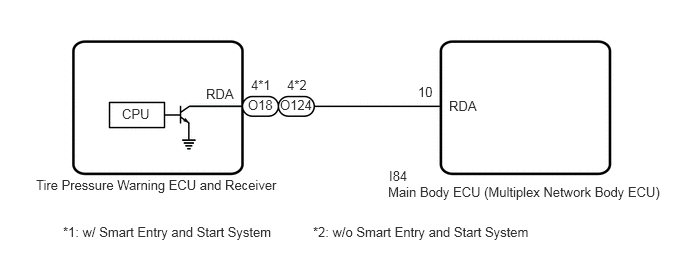
The main body ECU (multiplex network body ECU) and tire pressure warning ECU and receiver communicate by direct line. If a malfunction occurs in this communication signal, B1247 is output by the main body ECU (multiplex network body ECU).
| DTC No. | Detection Item | DTC Detection Condition | Trouble Area | Note |
|---|---|---|---|---|
| B1247 | Tire Pressure Monitor Receiver Communication Stop | Communication between the tire pressure warning ECU and receiver and main body ECU (multiplex network body ECU) is interrupted for 10 seconds or more. | ·
Tire pressure warning ECU and receiver ·
Wire harness or connector ·
Main body ECU (Multiplex network body ECU) |
This DTC is for main body ECU (multiplex network body ECU) |
WIRING DIAGRAM
CAUTION / NOTICE / HINT
- NOTICE:
- ·
When replacing the tire pressure warning ECU and receiver, read the transmitter IDs and number of the transmitters (4 or 5) stored in the old ECU using the GTS and write them down before removal.
·It is necessary to perform initializationSuspension>TIRE PRESSURE MONITORING>TIRE PRESSURE WARNING SYSTEM (for Gasoline Model (for Type A))>INITIALIZATION202304,999999,_53,_080780,_0393955,RM100000002BB37, after registrationSuspension>TIRE PRESSURE MONITORING>TIRE PRESSURE WARNING SYSTEM (for Gasoline Model (for Type A))>REGISTRATION202304,999999,_53,_080780,_0393955,RM100000002B0BZ, of the transmitter IDs into the tire pressure warning ECU and receiver after the ECU has been replaced.
·Before replacing the main body ECU (multiplex network body ECU), refer to Service Bulletin.*
*: w/ Smart Entry and Start System
PROCEDURE
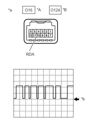
| *A | w/ Smart Entry and Start System |
| *B | w/o Smart Entry and Start System |
| *a | Component with harness connected
(Tire Pressure Warning ECU and Receiver) |
| *b | GND |
Using an oscilloscope, check the waveform.
- NOTICE:
-
With the connector connected, check from the backside of the connector.
- OK:
w/ Smart Entry and Start System Tester Connection Tool Setting Range Condition Specified Condition O18-4 (RDA) - Body ground 5 V/DIV.5 ms./DIV. Ignition switch ON Waveform generation
w/o Smart Entry and Start System Tester Connection Tool Setting Range Condition Specified Condition O124-4 (RDA) - Body ground 5 V/DIV.5 ms./DIV. Ignition switch ON Waveform generation
- Result:
Result Proceed to Waveform is as shown in the illustration. (Waveform alternates between 10.5 V or higher and 0.5 V or less) A Waveform does not change from 10.5 V or higher B Waveform does not change from 0.5 V or less C
A
B
C
Disconnect the O18*1 or O124*2 tire pressure warning ECU and receiver connector.
*1: w/ Smart Entry and Start System
*2: w/o Smart Entry and Start System
Measure the voltage according to the value(s) in the table below.
- Standard Voltage:
w/ Smart Entry and Start System Tester Connection Condition Specified Condition O18-4 (RDA) - Body ground Ignition switch ON 10.5 V or higher
w/o Smart Entry and Start System Tester Connection Condition Specified Condition O124-4 (RDA) - Body ground Ignition switch ON 10.5 V or higher
- Result:
Proceed to OK NG
OK
NG
Turn the ignition switch off.
Disconnect the I84 main body ECU (multiplex network body ECU) connector.
Measure the resistance according to the value(s) in the table below.
- Standard Resistance:
w/ Smart Entry and Start System Tester Connection Condition Specified Condition I84-10 (RDA) - O18-4 (RDA) Always Below 1 Ω I84-10 (RDA) or O18-4 (RDA) - Body ground Always 10 kΩ or higher
w/o Smart Entry and Start System Tester Connection Condition Specified Condition I84-10 (RDA) - O124-4 (RDA) Always Below 1 Ω I84-10 (RDA) or O124-4 (RDA) - Body ground Always 10 kΩ or higher
- Result:
Proceed to OK NG
OK
NG