RM3660EC _95 ADAS / AD _139716 ADVANCED DRIVER ASSISTANCE SYSTEM _0601171 DYNAMIC RADAR CRUISE CONTROL SYSTEM(for NR Series Engine) C

ADVANCED DRIVER ASSISTANCE SYSTEM  DYNAMIC RADAR CRUISE CONTROL SYSTEM(for NR Series Engine)  P057162  Brake Switch "A" Signal Compare Failure  


DESCRIPTION

When the brake pedal is depressed, the stop light switch assembly outputs a signal to the ECM. The ECM uses this signal to control cancellation of vehicle speed by the dynamic radar cruise control. When the ECM determines that terminals STP and ST1 of the stop light switch assembly are both less than 1 V, DTC P057162 is stored.

DTC No. Detection Item DTC Detection Condition Trouble Area MIL DTC Output from Note
P057162 Brake Switch "A" Signal Compare Failure When the ignition switch is ON and the dynamic radar cruise control system is operating, the ECM detects that the voltage at terminal STP and ST1- are both less than 1 V for approximately 0.5 seconds or more.
·

Harness or connector

·

Stop light switch assembly

·

ECM


Does not come on Radar Cruise1 SAE Code: P0571

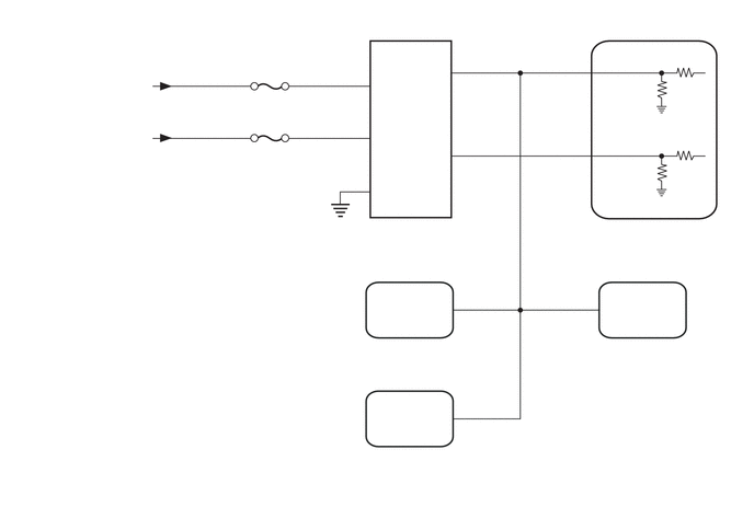
WIRING DIAGRAM

A460859
0.406,0.708 1.448,0.917 1.042,0.208 10 false from J/B-B Fuse 0.094,1.188 1.5,1.427 1.406,0.24 10 false from IG2-NO. 2 Relay 2.396,0.896 4.385,1.094 1.99,0.198 10 false STOP 2.146,1.406 4.135,1.604 1.99,0.198 10 false ECU-IG2 NO. 3 3.031,2.281 5.021,2.479 1.99,0.198 10 false Stop Light Switch Assembly 3.042,2.115 5.031,2.313 1.99,0.198 10 false A53 3.573,0.74 3.729,0.938 0.156,0.198 10 false B 3.573,1.219 3.729,1.417 0.156,0.198 10 false B 3.552,1.719 3.896,1.906 0.344,0.188 10 false GND 4.156,0.604 4.313,0.802 0.156,0.198 10 false L 4.167,1.385 4.323,1.583 0.156,0.198 10 false L 3.396,0.625 3.615,0.865 0.219,0.24 10 false 7 3.406,1.125 4.271,1.417 0.865,0.292 10 false 6 3.396,1.625 3.99,1.885 0.594,0.26 10 false 2 4.344,0.5 4.948,0.729 0.604,0.229 10 false 3 4.344,1.302 4.948,1.51 0.604,0.208 10 false 5 5.688,0.5 6.146,0.698 0.458,0.198 10 false STP 5.677,1.281 6.021,1.458 0.344,0.177 10 false ST1- 5.49,0.5 5.656,0.708 0.167,0.208 10 false 9 5.417,1.292 5.646,1.49 0.229,0.198 10 false 10 6.188,2.104 6.542,2.271 0.354,0.167 10 false ECM 5.833,2.104 6.125,2.292 0.292,0.188 10 false A46 2.135,3.229 4.948,3.438 2.813,0.208 10 false Skid Control ECU (Brake Actuator Assembly) 2.146,3.063 4.135,3.26 1.99,0.198 10 false A51 4,2.813 4.313,3.031 0.313,0.219 10 false STP 4.354,2.74 4.563,2.917 0.208,0.177 10 false 41 5.5,2.75 5.708,2.958 0.208,0.208 10 false 24 5.417,3.271 6.938,3.656 1.521,0.385 10 false Certification ECU (Smart Key ECU Assembly) 5.729,2.844 6.115,3.021 0.385,0.177 10 false STP1 5.406,3.125 5.719,3.313 0.313,0.188 10 false O61 2.667,4.26 5.365,4.604 2.698,0.344 10 false Shift Lock Control ECU (Shift Lock Control Unit Assembly) 2.677,4.083 2.927,4.281 0.25,0.198 10 false I18 4.354,3.781 4.49,3.979 0.135,0.198 10 false 4 4,3.854 4.323,4.042 0.323,0.188 10 false STP

CAUTION / NOTICE / HINT

NOTICE:
·

Inspect the fuses for circuits related to this system before performing the following procedure.

·

Before replacing the ECM, refer to Service Bulletin.


PROCEDURE
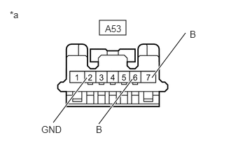
1.CHECK HARNESS AND CONNECTOR (STOP LIGHT SWITCH ASSEMBLY - POWER SOURCE AND BODY GROUND)
A395526C22
1.479,0.302 1.875,0.521 0.396,0.219 0.792,1.823 1.292,1.156 true 1.469,1.844 1.969,1.177 true 2.26,1.156 2.76,0.49 true 0.146,0.135 0.458,0.292 0.313,0.156 10 false *a 0.615,1.844 1.073,2.042 0.458,0.198 10 false GND 1.427,1.844 1.885,2.042 0.458,0.198 10 false B 2.823,0.427 3.281,0.625 0.458,0.198 10 false B 1.563,0.344 2.021,0.542 0.458,0.198 10 false A53
*a Front view of wire harness connector
(to Stop Light Switch Assembly)


a.

Disconnect the A53 stop light switch assembly connector.


b.

Measure the resistance according to the value(s) in the table below.

Standard Resistance:
Tester Connection Condition Specified Condition
A53-2 (GND) - Body ground Always Below 1 Ω


c.

Measure the voltage according to the value(s) in the table below.

Standard Voltage:
Tester Connection Condition Specified Condition
A53-7 (B) - Body ground Always 11 to 14 V
A53-6 (B) - Body ground Ignition switch ON 11 to 14 V
A53-6 (B) - Body ground Ignition switch off Below 1 V


d.

Connect the A53 stop light switch assembly connector.


Result:
Proceed to
OK
NG


OK

2.INSPECT STOP LIGHT SWITCH ASSEMBLY

NG

REPAIR OR REPLACE HARNESS OR CONNECTOR

2.INSPECT STOP LIGHT SWITCH ASSEMBLY

OK

3.CHECK HARNESS AND CONNECTOR (STOP LIGHT SWITCH ASSEMBLY - ECM)

NG

3.CHECK HARNESS AND CONNECTOR (STOP LIGHT SWITCH ASSEMBLY - ECM)
a.

Disconnect the A46 ECM connector.


b.

Disconnect the A51 skid control ECU (brake actuator assembly) connector.


c.

Disconnect the O61 certification ECU (smart key ECU assembly) connector.


d.

Disconnect the I18 shift lock control ECU (shift lock control unit assembly) connector.


e.

Measure the resistance according to the value(s) in the table below.

Standard Resistance:
Tester Connection Condition Specified Condition
A53-3 (L) - A46-9 (STP) Always Below 1 Ω
A53-5 (L) - A46-10 (ST1-) Always Below 1 Ω
A53-3 (L) or A46-9 (STP) - Body ground Always 10 kΩ or higher
A53-5 (L) or A46-10 (ST1-) - Body ground Always 10 kΩ or higher


Result:
Proceed to
OK
NG


OK

NG

REPAIR OR REPLACE HARNESS OR CONNECTOR