ADVANCED DRIVER ASSISTANCE SYSTEM FRONT CAMERA SYSTEM(for NR Series Engine) C1AAE00 Front Recognition Camera Heater Malfunction
DESCRIPTION
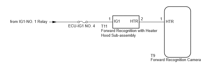
The forward recognition camera controls the flow of current to the forward recognition with heater hood sub-assembly.
If the forward recognition camera detects a malfunction in the forward recognition with heater hood sub-assembly circuit, it will store this DTC.
| DTC No. | Detection Item | DTC Detection Condition | Trouble Area |
|---|---|---|---|
| C1AAE00 | Front Recognition Camera Heater Malfunction | Either of the following conditions is met after 10 seconds have elapsed since the ignition switch was turned to ON:
·
Short to +B detected in the forward recognition with heater hood sub-assembly circuit for 1 second or more cumulatively ·
Open or short to ground detected in the forward recognition with heater hood sub-assembly circuit for 5 seconds or more |
·
Forward recognition with heater hood sub-assembly ·
Forward recognition camera ·
Wire harness or connector |
WIRING DIAGRAM
CAUTION / NOTICE / HINT
- NOTICE:
- ·
Inspect the fuses for circuits related to this system before performing the following procedure.
·When replacing the forward recognition camera, always replace it with a new one. If a forward recognition camera which was installed to another vehicle is used, the information stored in the forward recognition camera will not match the information from the vehicle. As a result, a DTC may be stored.
·If the forward recognition camera has been replaced with a new one, be sure to perform forward recognition camera adjustment.
- HINT:
-
Forward recognition camera adjustment can be performed by using either One Time Recognition or Sequential Recognition.
-
One Time Recognition: Click hereADAS / AD>ADVANCED DRIVER ASSISTANCE SYSTEM>FRONT CAMERA (for NR Series Engine)>ADJUSTMENT (ONE TIME RECOGNITION)202304,999999,_95,_139716,_0584840,RM1000000029I36,
-
Sequential Recognition: Click hereADAS / AD>ADVANCED DRIVER ASSISTANCE SYSTEM>FRONT CAMERA (for NR Series Engine)>ADJUSTMENT (SEQUENTIAL RECOGNITION)202304,999999,_95,_139716,_0584840,RM1000000029I37,
PROCEDURE
Clear the DTCs.
- Chassis > Front Recognition Camera > Clear DTCs
- 50002 430
Make sure that the DTC detection conditions are met.
- HINT:
-
If the detection conditions are not met, the system cannot detect the malfunction.
Check for DTCs.
- Chassis > Front Recognition Camera > Trouble Codes
- 50001 430
- Result:
Result Proceed to DTC C1AAE00 is not output A DTC C1AAE00 is output B
A
B
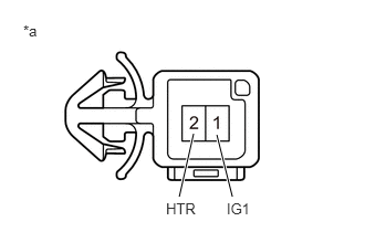
| *a | Component without harness connected
(Forward Recognition with Heater Hood Sub-assembly) |
Turn the ignition switch off.
Disconnect the forward recognition with heater hood sub-assembly connector.
Measure the resistance according to the value(s) in the table below.
- Standard Resistance:
Tester Connection Condition Specified Condition 1 (IG1) - 2 (HTR) Ignition switch off 28.5 to 31.5 Ω
Connect the forward recognition with heater hood sub-assembly connector.
- Result:
Proceed to OK NG
OK
NG
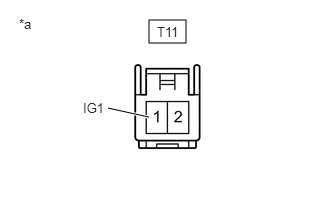
| *a | Front view of wire harness connector
(to Forward Recognition with Heater Hood Sub-assembly) |
Disconnect the T11 forward recognition with heater hood sub-assembly connector.
Measure the voltage according to the value(s) in the table below.
- Standard Voltage:
Tester Connection Condition Specified Condition T11-1 (IG1) - Body ground Ignition switch ON 8 to 16 V Ignition switch off Below 1.5 V
Connect the T11 forward recognition with heater hood sub-assembly connector.
- Result:
Proceed to OK NG
OK
NG
Disconnect the T11 forward recognition with heater hood sub-assembly connector.
Disconnect the T9 forward recognition camera connector.
Measure the resistance according to the value(s) in the table below.
- Standard Resistance:
Tester Connection Condition Specified Condition T11-2 (HTR) - T9-1 (HTR) Always Below 1 Ω T11-2 (HTR) or T9-1 (HTR) - Body ground Always 10 kΩ or higher
Connect the T9 forward recognition camera connector.
Connect the T11 forward recognition with heater hood sub-assembly connector.
- Result:
Proceed to OK NG
OK
NG