AUDIO / VIDEO AUDIO AND VISUAL SYSTEM(for 10.25 Inch Display) B157913 Voice Recognition Microphone1 Circuit Open
DESCRIPTION
The telephone microphone assembly LH is connected to the radio and display receiver assembly via voice recognition microphone 1 signal detection line.
This DTC is stored when the radio and display receiver assembly detects disconnection of telephone microphone assembly LH.
| DTC No. | Detection Item | DTC Detection Condition | Trouble Area |
|---|---|---|---|
| B157913 | Voice Recognition Microphone1 Circuit Open | Voice recognition microphone 1 terminal (SNS) disconnected
(2 trip detection logic) |
·
Telephone microphone assembly LH ·
Radio and display receiver assembly ·
Harness or connector ·
Telematics transceiver |
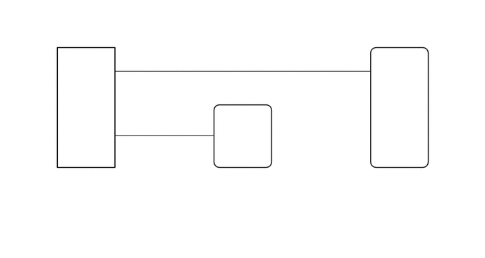
WIRING DIAGRAM
CAUTION / NOTICE / HINT
- NOTICE:
-
Depending on the parts that are replaced during vehicle inspection or maintenance, performing initialization, registration or calibration may be needed.
PROCEDURE
Disconnect the T2 telephone microphone assembly LH connector.
Disconnect the I209 radio and display receiver assembly connector.
Disconnect the I72 telematics transceiver connector.
Measure the resistance according to the value(s) in the table below.
- Standard Resistance:
Tester Connection Condition Specified Condition *1: except M15C-FKS, 8ZR-FXE GTMC Made
*2: for M15C-FKS, 8ZR-FXE GTMC Made
T2-5 (SNS1) - I209-25 (SNS)*1 Always Below 1 Ω T2-5 (SNS1) - I209-25 (SNS1)*2 Always Below 1 Ω T2-4 (MO1-) - I72-7 (MCI-) Always Below 1 Ω T2-5 (SNS1) or I209-25 (SNS) - Body ground*1 Always 10 kΩ or higher T2-5 (SNS1) or I209-25 (SNS1) - Body ground*2 Always 10 kΩ or higher T2-4 (MO1-) or I72-7 (MCI-) - Body ground Always 10 kΩ or higher
- Result:
Proceed to OK NG
OK
NG
With the telematics transceiver connector connected, disconnect the T2 telephone microphone assembly LH connector.
Measure the resistance according to the value(s) in the table below.
- Standard Resistance:
Tester Connection Condition Specified Condition T2-4 (MO1-) - Body ground Always Below 1 Ω
- Result:
Proceed to OK NG
OK
NG
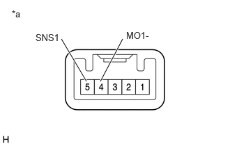
| *a | Component without harness connected
(Telephone microphone assembly LH) |
Remove the telephone microphone assembly LH.
Measure the resistance according to the value(s) in the table below.
- Standard Resistance:
Tester Connection Condition Specified Condition 5 (SNS1) - 4 (MO1-) Always Below 1 Ω
- Result:
Proceed to OK NG
OK
NG