NAVIGATION / MULTI INFO DISPLAY NAVIGATION SYSTEM(for 10.25 Inch Display) U11D087 Lost Local Communication with MET Missing Message
DESCRIPTION
These DTCs are stored when the navigation receiver assembly detects a communication malfunction with the combination meter assembly.
| DTC No. | Detection Item | DTC Detection Condition | Trouble Area | DTC Output from | Priority |
|---|---|---|---|---|---|
| U11D087 | Lost Local Communication with MET Missing Message | Communication malfunction between navigation receiver assembly and combination meter assembly for 30 seconds or more
(2 trip detection logic) |
·
Open or short in local bus circuit ·
Harness or connector ·
Combination meter assembly ·
Navigation Receiver Assembly |
Navigation System | A |
WIRING DIAGRAM
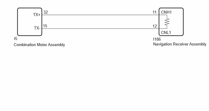
CAUTION / NOTICE / HINT
- NOTICE:
- ·
Depending on the parts that are replaced during vehicle inspection or maintenance, performing initialization, registration or calibration may be needed.
·Inspect the fuses for circuits related to this system before performing the following procedure.
·When replacing the combination meter assembly, make sure to replace it with a new one. If a combination meter assembly which was installed to another vehicle is used, the information stored in the combination meter assembly will not match the information from the vehicle and a DTC may be stored.
·Before measuring the resistance of the CAN bus, turn the ignition switch off and leave the vehicle for 1 minute or more without operating the key, switches or opening or closing the doors. After that, disconnect the cable from the negative (-) battery terminal and leave the vehicle for 1 minute or more before measuring the resistance.
·After turning the ignition switch off, waiting time may be required before disconnecting the cable from the negative (-) battery terminal. Therefore make sure to read the disconnecting the cable from the negative (-) battery terminal notices before proceeding with work.
- HINT:
- ·
Before disconnecting related connectors for inspection, push in on the connector body to check that each connector is not loose or disconnected.
·When a connector is disconnected, check that the terminals and connector body are not cracked, deformed or corroded.
·When the cable is disconnected / reconnected to the battery terminal, systems temporarily stop operating. However, each system has a function that completes learning the first time the system is used.
PROCEDURE
Pre-procedure1
Disconnect the cable from the negative (-) battery terminal.
Disconnect the I5 combination meter assembly connector.
Procedure1
Measure the resistance according to the value(s) in the table below.
- Standard Resistance:
Tester Connection Condition Specified Condition I5-32 (TX+) - I5-15 (TX-) Cable disconnected from negative (-) battery terminal 108 to 132 Ω I5-32 (TX+) - I26-4 (CG) Cable disconnected from negative (-) battery terminal 200 Ω or higher I5-15 (TX-) - I26-4 (CG) Cable disconnected from negative (-) battery terminal 200 Ω or higher I5-32 (TX+) - I26-16 (BAT) Cable disconnected from negative (-) battery terminal 6 kΩ or higher I5-15 (TX-) - I26-16 (BAT) Cable disconnected from negative (-) battery terminal 6 kΩ or higher
- Result:
Proceed to OK NG
Post-procedure1
None
OK
NG
Pre-procedure1
Disconnect the cable from the negative (-) battery terminal.
Disconnect the I186 navigation receiver assembly connector.
Procedure1
Measure the resistance according to the value(s) in the table below.
- Standard Resistance:
Tester Connection Condition Specified Condition I186-11 (CNH1) - I186-12 (CNL1) Cable disconnected from negative (-) battery terminal 108 to 132 Ω I186-11 (CNH1) - I26-4 (CG) Cable disconnected from negative (-) battery terminal 200 Ω or higher I186-12 (CNL1) - I26-4 (CG) Cable disconnected from negative (-) battery terminal 200 Ω or higher I186-11 (CNH1) - I26-16 (BAT) Cable disconnected from negative (-) battery terminal 6 kΩ or higher I186-12 (CNL1) - I26-16 (BAT) Cable disconnected from negative (-) battery terminal 6 kΩ or higher
- Result:
Proceed to OK NG
Post-procedure1
None
OK
NG