NETWORKING CXPI COMMUNICATION SYSTEM TERMINALS OF ECU
- NOTICE:
- ·
Do not remove or install the power distribution box assembly with the negative (-) auxiliary battery terminal connected.
·After turning the ignition switch off, waiting time may be required before disconnecting the cable from the negative (-) auxiliary battery terminal. Therefore, make sure to read the disconnecting the cable from the negative (-) auxiliary battery terminal notices before proceeding with work.
·When disconnecting the cable from the negative (-) auxiliary battery terminal while performing repairs, some systems need to be initialized after the cable is reconnected.
CHECK POWER DISTRIBUTION BOX ASSEMBLY AND MAIN BODY ECU (MULTIPLEX NETWORK BODY ECU)
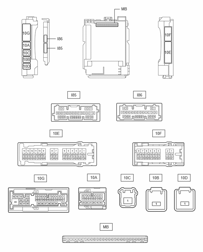
Remove the main body ECU (multiplex network body ECU).
Reconnect the power distribution box assembly connectors.
Measure the voltage and resistance according to the value(s) in the table below.
| Terminal No. (Symbol) | Terminal Description | Condition | Specified Condition |
|---|---|---|---|
| MB-13 (GND1) - Body ground | Ground | Always | Below 1 Ω |
| MB-14 (GND2) - Body ground | Ground | Always | Below 1 Ω |
| MB-26 (BECU) - Body ground | Auxiliary battery power supply | Always*1
Ignition switch off*2 |
11 to 14 V |
| MB-27 (IGR) - Body ground | IG power supply | Ignition switch off | Below 1 V |
| Ignition switch ON | 11 to 14 V |
*1: for Gasoline Model
*2: for HEV Model
Install the main body ECU (multiplex network body ECU).
Measure the voltage and check for pulses according to the value(s) in the table below.
| Terminal No. (Symbol) | Terminal Description | Condition | Specified Condition |
|---|---|---|---|
| 10A-9 - Body ground | CXPI communication line | Ignition switch ON | Pulse generation |
CHECK WINDSHIELD WIPER RELAY ASSEMBLY
for Gasoline Model: Click hereVehicle Exterior>WIPER / WASHER>WIPER AND WASHER SYSTEM (for Gasoline Model)>TERMINALS OF ECU202304,999999,_59,_080767,_0391512,RM100000002B8RR,
for HV Model: Click hereVehicle Exterior>WIPER / WASHER>WIPER AND WASHER SYSTEM (for HV Model)>TERMINALS OF ECU202304,202307,_59,_080767,_0391511,RM100000002B8NX,202307,999999,_59,_080767,_0391511,RM100000002CUMG,