WINDOW / GLASS WINDOW DEFOGGER SYSTEM(for NR Series Engine) Rear Window Defogger System does not Operate
DESCRIPTION
When the rear window defogger switch on the air conditioning control assembly is pressed, the operation signal is transmitted to the air conditioning amplifier assembly via LIN communication. When the air conditioning amplifier assembly receives the signal, it turns on the DEF relay to operate the window defogger system.
WIRING DIAGRAM
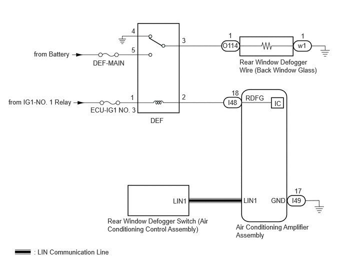
CAUTION / NOTICE / HINT
- NOTICE:
- ·
Inspect the fuses for circuits related to this system before performing the following procedure.
·If the battery voltage becomes low, battery load control will operate in order to ensure sufficient power is supplied to the power steering system. In this case, the window defogger system may not operate.
PROCEDURE
Check the air conditioning system.
- HINT:
-
Both the window defogger system operation signal and air conditioning system operation signal are transmitted to the air conditioning amplifier assembly via the same communication line.
- OK:
The air conditioning system operates normally.
- Result:
Proceed to OK NG
OK
NG
for Gasoline Model (NR Series) with Manual Air Conditioning System for Electrical Control Type: Click hereVehicle Interior>HEATING / AIR CONDITIONING>AIR CONDITIONING SYSTEM (for Gasoline Model (NR Series) with Manual Air Conditioning System for Electrical Control Type)>HOW TO PROCEED WITH TROUBLESHOOTING202304,999999,_58,_080733,_0591215,RM100000002AH6B,
for Gasoline Model (NR Series) with Manual Air Conditioning System for Mechanical Control Type: Click hereVehicle Interior>HEATING / AIR CONDITIONING>AIR CONDITIONING SYSTEM (for Gasoline Model (NR Series) with Manual Air Conditioning System for Mechanical Control Type)>HOW TO PROCEED WITH TROUBLESHOOTING202304,999999,_58,_080733,_0591216,RM100000002AH7T,
Connect the GTS to the DLC3.
Turn the ignition switch to ON.
Turn the GTS on.
Enter the following menus: Body Electrical / Air Conditioner / Active Test.
Perform the Active Test according to the display on the GTS.
- Body Electrical > Air Conditioner > Active Test
-
Tester Display Measurement Item Control Range Diagnostic Note Defogger Relay (Rear) Rear window defogger wire (Back window glass) OFF or ON -
- Body Electrical > Air Conditioner > Active Test
-
Tester Display Defogger Relay (Rear) - 50004 121 22
- OK:
The window defogger system operates normally.
- Result:
Proceed to OK NG
OK
NG
Replace the air conditioning control assembly with a new or known good one.
Check that the window defogger system operates normally.
- OK:
The window defogger system operates normally.
- Result:
Proceed to OK NG
OK
NG
Inspect the DEF relay.
- Result:
Proceed to OK NG
OK
NG
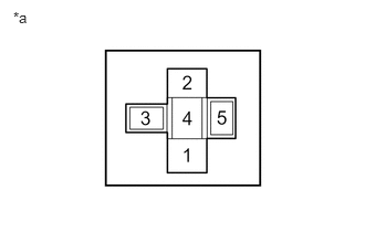
| *a | DEF Relay Holder |
Remove the DEF relay from the No. 1 engine room relay block and No. 1 engine room junction block.
Measure the voltage according to the value(s) in the table below.
- Standard Voltage:
Tester Connection Condition Specified Condition DEF relay holder terminal 1 - Body ground Ignition switch ON 11 to 14 V DEF relay holder terminal 5 - Body ground Always 11 to 14 V
- Result:
Proceed to OK NG
OK
NG
| *a | DEF Relay Holder |
Remove the DEF relay from the No. 1 engine room relay block and No. 1 engine room junction block.
Disconnect the I48 air conditioning amplifier assembly connector.
Measure the resistance according to the value(s) in the table below.
- Standard Resistance:
Tester Connection Condition Specified Condition DEF relay holder terminal 2 - I48-18 (RDFG) Always Below 1 Ω DEF relay holder terminal 2 or I48-18 (RDFG) - Body ground Always 10 kΩ or higher
- Result:
Proceed to OK NG
OK
NG
| *a | DEF Relay Holder |
Remove the DEF relay from the No. 1 engine room relay block and No. 1 engine room junction block.
Disconnect the O114 rear window defogger wire (back window glass) connector.
Measure the resistance according to the value(s) in the table below.
- Standard Resistance:
Tester Connection Condition Specified Condition DEF relay holder terminal 3 - O114-1 Always Below 1 Ω DEF relay holder terminal 3 or O114-1 - Body ground Always 10 kΩ or higher
- Result:
Proceed to OK NG
OK
NG
Disconnect the w1 rear window defogger wire (back window glass) connector.
Measure the resistance according to the value(s) in the table below.
- Standard Resistance:
Tester Connection Condition Specified Condition W1-1 - Body ground Always Below 1 Ω
- Result:
Proceed to OK NG
OK
NG
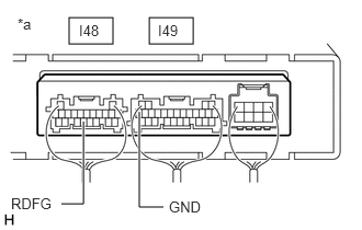
| *a | Component with harness connected
(Air Conditioning Amplifier Assembly) |
Reconnect the I48 and I49 air conditioning amplifier assembly connectors.
Reinstall the DEF relay.
Remove the air conditioning amplifier assembly with its connectors still connected.
Measure the voltage according to the value(s) in the table below.
- Standard Voltage:
Tester Connection Condition Specified Condition I48-18 (RDFG) - I49-17 (GND) Ignition switch ON, rear window defogger switch on Below 1 V I48-18 (RDFG) - I49-17 (GND) Ignition switch ON, rear window defogger switch off 11 to 14 V
- Result:
Proceed to OK NG
OK
NG