POWER ASSIST SYSTEMS POWER STEERING ECU REMOVAL
CAUTION / NOTICE / HINT
The necessary procedures (adjustment, calibration, initialization, or registration) that must be performed after parts are removed and installed, or replaced during power steering ECU with motor assembly removal/installation are shown below.
| Replaced Part or Performed Procedure | Necessary Procedure | Effect/Inoperative Function when Necessary Procedure not Performed | Link |
|---|---|---|---|
| Power steering ECU assembly | Update ECU security key | Vehicle Control History (RoB) are stored | ( 202304,999999,_V1,_143216,_0598316,RM100000002B3ML,) 202304,999999,_V1,_143216,_0598316,RM100000002B3ML,)
|
| ECU configuration | ·
Vehicle Control History (RoB) are stored ·
EPS warning light illuminates |
(202304,999999,_V1,_143216,_0598316,RM100000002B3ML,)
|
|
| Perform power steering ECU initial setting (assist map writing) | ·
Vehicle Control History (RoB) are stored ·
EPS warning light illuminates |
(202304,202307,_55,_080761,_0392075,RM100000002B8OH,202307,999999,_55,_080761,_0392075,RM100000002CNVO,)
|
|
| End position initial setting | - |
| Replaced Part or Performed Procedure | Necessary Procedure | Effect/Inoperative Function when Necessary Procedure not Performed | Link |
|---|---|---|---|
| Power steering ECU assembly | except NR Series
Update ECU security key |
Vehicle Control History (RoB) are stored | (202304,999999,_V1,_143216,_0598316,RM100000002B3ML,)
|
except NR Series
ECU configuration |
·
Vehicle Control History (RoB) are stored ·
EPS warning light illuminates |
(202304,999999,_V1,_143216,_0598316,RM100000002B3MK,)
|
|
except NR Series
Perform power steering ECU initial setting (assist map writing) |
·
Vehicle Control History (RoB) are stored ·
EPS warning light illuminates |
(202304,999999,_55,_080761,_0392052,RM100000002B8PZ,)
|
|
except NR Series
End position initial setting |
- | (202304,999999,_55,_080761,_0392052,RM100000002B8PZ,)
|
|
for NR Series
Perform power steering ECU initial setting (torque sensor zero point calibration and assist map writing) |
·
Vehicle Control History (RoB) are stored ·
Steering effort different between turning steering wheel left and right ·
EPS warning light illuminates |
(202304,999999,_55,_080761,_0392052,RM100000002B8PZ,)
|
CAUTION / NOTICE / HINT
- NOTICE:
-
After turning the ignition switch (for Gasoline Model) or power switch (for HV Model) off, waiting time may be required before disconnecting the cable from the negative (-) auxiliary battery terminal. Therefore, make sure to read the disconnecting the cable from the negative (-) auxiliary battery terminal notices before proceeding with work.
- HINT:
-
When the cable is disconnected / reconnected to the battery terminal, systems temporarily stop operating. However, each system has a function that completes learning the first time the system is used.
Learning completes when vehicle is driven (for HV Model) Effect/Inoperative Function when Necessary Procedure not Performed Necessary Procedures Link Front Camera System Drive the vehicle straight ahead at 15 km/h (9 mph) or more for 1 second or more. ( 202304,999999,_95,_139716,_0584193,RM1000000029F4C,)
Learning completes when vehicle is driven (for Gasoline Model) Effect/Inoperative Function when Necessary Procedure not Performed Necessary Procedures Link Stop and Start System Idle the engine for approximately 5 to 60 minutes or drive the vehicle until stop and start control is permitted ( 201906,999999,_51,_080774,_0393362,RM100000001HXHC,)
Pre-collision System Perform steering sensor zero point calibration ( 202304,999999,_95,_139716,_0601175,RM100000002BFOE,)
Lane Tracing Assist System Front Camera System Drive the vehicle straight ahead at 15 km/h (9 mph) or more for 1 second or more. ( 202304,999999,_95,_139716,_0584193,RM1000000029F4C,)
PROCEDURE

 1.REMOVE STEERING COLUMN ASSEMBLY
2.REMOVE UPPER STEERING COLUMN BRACKET WITH SWITCH ASSEMBLY (w/o Smart Entry and Start System)
45020B
3.REMOVE STEERING LOCK ACTUATOR ASSEMBLY (w/ Smart Entry and Start System with Steering Lock Actuator Assembly)
89650F
4.REMOVE POWER STEERING ECU WITH MOTOR ASSEMBLY
- NOTICE:
- ·
Do not drop the power steering ECU with motor assembly, strike it with tools or subject it to impacts.
·If the power steering ECU with motor assembly is subjected to an impact, replace it with a new one.
·Do not pull the wire harness of the electric power steering column sub-assembly.
·Do not allow any moisture to come into contact with the power steering ECU with motor assembly.
·Do not loosen any bolts not mentioned in the procedure.
·Do not allow any foreign matter to contaminate the power steering ECU with motor assembly.
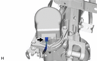
Disconnect the connector.
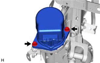
Remove the 2 bolts and power steering ECU with motor assembly from the electric power steering column sub-assembly.
45254B
5.REMOVE ELECTRIC POWER STEERING MOTOR SHAFT DAMPER
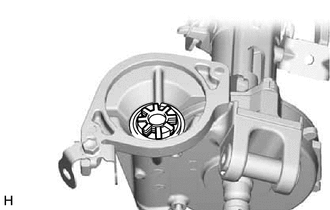
Remove the electric power steering motor shaft damper from the electric power steering column sub-assembly.