TIRE PRESSURE MONITORING TIRE PRESSURE WARNING SYSTEM(for Gasoline Model (for Type A)) C2111 Transmitter ID1 Operation Stop C2112 Transmitter ID2 Operation Stop C2113 Transmitter ID3 Operation Stop C2114 Transmitter ID4 Operation Stop
DESCRIPTION
The tire pressure warning valve and transmitters that are installed in the tire and wheel assemblies measure the tire pressure of each wheel. The measured values are transmitted to the tire pressure warning ECU and receiver in the vehicle as radio waves. The ECU compares the measured tire pressure values with the tire pressure threshold. When the measured tire pressure value is less than this threshold, the warning light in the combination meter assembly illuminates. The tire pressure warning ECU and receiver stores a DTC when the tire pressure warning valve and transmitter stops transmitting signals. The signals can be forcibly transmitted by releasing the tire pressure rapidly. The stored DTCs are cleared when signal transmission resumes.
| DTC No. | Detection Item | DTC Detection Condition | Trouble Area | Note |
|---|---|---|---|---|
| C2111 | Transmitter ID1 Operation Stop | Tire pressure warning valve and transmitters stop transmitting signals | ·
Tire pressure warning valve and transmitter ·
Tire pressure warning ECU and receiver |
- |
| C2112 | Transmitter ID2 Operation Stop | Tire pressure warning valve and transmitters stop transmitting signals | ·
Tire pressure warning valve and transmitter ·
Tire pressure warning ECU and receiver |
- |
| C2113 | Transmitter ID3 Operation Stop | Tire pressure warning valve and transmitters stop transmitting signals | ·
Tire pressure warning valve and transmitter ·
Tire pressure warning ECU and receiver |
- |
| C2114 | Transmitter ID4 Operation Stop | Tire pressure warning valve and transmitters stop transmitting signals | ·
Tire pressure warning valve and transmitter ·
Tire pressure warning ECU and receiver |
- |
- HINT:
-
It is necessary to perform the following procedure to identify the tire pressure warning valve and transmitter that is malfunctioning because it cannot be identified by the output DTC.
WIRING DIAGRAM
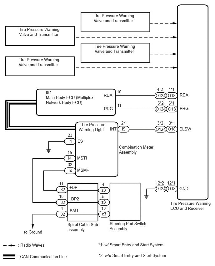
PROCEDURE
Set the tire pressure to the specified value.
Turn the ignition switch off.
Connect the GTS to the DLC3.
Turn the ignition switch to ON.
Turn the GTS on.
Enter the following menus: Chassis / Tire Pressure Monitor / Data List.
Read the Data List according to the display on the GTS.
- Chassis > Tire Pressure Monitor > Data List
-
Tester Display Measurement Item Range Normal Condition Diagnostic Note ID 1 Tire Inflation Pressure ID1 tire inflation pressure min.: Absolute pressure (abs) / 0 kPa (0 kgf/cm2, 0 psi), Relative pressure (Gauge) / 0 kPa (0 kgf/cm2, 0 psi)
max.: Absolute pressure (abs) / 480 kPa (4.9 kgf/cm2, 70 psi), Relative pressure (Gauge) / 380 kPa (3.9 kgf/cm2, 55 psi)Actual tire inflation pressure If N/A is displayed, data has not been received.*1 ID 2 Tire Inflation Pressure ID2 tire inflation pressure min.: Absolute pressure (abs) / 0 kPa (0 kgf/cm2, 0 psi), Relative pressure (Gauge) / 0 kPa (0 kgf/cm2, 0 psi)
max.: Absolute pressure (abs) / 480 kPa (4.9 kgf/cm2, 70 psi), Relative pressure (Gauge) / 380 kPa (3.9 kgf/cm2, 55 psi)Actual tire inflation pressure If N/A is displayed, data has not been received.*1 ID 3 Tire Inflation Pressure ID3 tire inflation pressure min.: Absolute pressure (abs) / 0 kPa (0 kgf/cm2, 0 psi), Relative pressure (Gauge) / 0 kPa (0 kgf/cm2, 0 psi)
max.: Absolute pressure (abs) / 480 kPa (4.9 kgf/cm2, 70 psi), Relative pressure (Gauge) / 380 kPa (3.9 kgf/cm2, 55 psi)Actual tire inflation pressure If N/A is displayed, data has not been received.*1 ID 4 Tire Inflation Pressure ID4 tire inflation pressure min.: Absolute pressure (abs) / 0 kPa (0 kgf/cm2, 0 psi), Relative pressure (Gauge) / 0 kPa (0 kgf/cm2, 0 psi)
max.: Absolute pressure (abs) / 480 kPa (4.9 kgf/cm2, 70 psi), Relative pressure (Gauge) / 380 kPa (3.9 kgf/cm2, 55 psi)Actual tire inflation pressure If N/A is displayed, data has not been received.*1
- HINT:
-
*1: It may take a few minutes until the values are displayed. If the values are not displayed after a few minutes, perform troubleshooting according to the inspection procedure for DTCs C2121 to C2124.
- Chassis > Tire Pressure Monitor > Data List
-
Tester Display ID 1 Tire Inflation Pressure ID 2 Tire Inflation Pressure ID 3 Tire Inflation Pressure ID 4 Tire Inflation Pressure - 50003 203 36,37,38,39
Rapidly reduce the tire pressure for each wheel at least 40 kPa (0.4 kgf/cm2, 5.8 psi) within 30 seconds.
Check that each "ID Tire Inflation Pressure" value displayed on the GTS has changed.
- OK:
Each "ID Tire Inflation Pressure" value displayed on the GTS changed to the actual tire inflation pressure value.
- NOTICE:
- ·
It may take a few minutes until the values are displayed.
·When an "ID Tire Inflation Pressure" value has not changed, reset the tire pressure to the appropriate specified value and rotate the tire 90 to 270 degrees. Then rapidly release the tire pressure and recheck the value.
After confirming that all of the tire "ID Tire Inflation Pressure" values displayed on the GTS have changed, set the tire pressure to the appropriate specified values.
- HINT:
-
If an "ID Tire Inflation Pressure" value displayed on the GTS has not changed after rechecking, inspect for another problem.
- Result:
Proceed to OK NG
OK
NG