TIRE PRESSURE MONITORING TIRE PRESSURE WARNING SYSTEM(for Gasoline Model (for Type A)) C2121 Transmitter ID 1 not Received (Main) C2122 Transmitter ID 2 not Received (Main) C2123 Transmitter ID 3 not Received (Main) C2124 Transmitter ID 4 not Received (Main) C2181 Transmitter ID 1 not Received (for Test Diagnosis) C2182 Transmitter ID 2 not Received (for Test Diagnosis) C2183 Transmitter ID 3 not Received (for Test Diagnosis) C2184 Transmitter ID 4 not Received (for Test Diagnosis)
DESCRIPTION
The tire pressure warning valve and transmitters that are installed in the tire and wheel assemblies measure the tire pressure of each wheel. The measured values are transmitted to the tire pressure warning ECU and receiver in the vehicle as radio waves. The ECU compares the measured tire pressure values with the tire pressure threshold. When the measured tire pressure value is less than this threshold, the warning light in the combination meter assembly illuminates.
The tire pressure warning valve and transmitters constantly send radio waves to the tire pressure warning ECU and receiver.
Under the conditions below, the tire pressure warning ECU and receiver is unable to receive the signals from the tire pressure warning valve and transmitters, and a DTC is stored.
Facilities or devices that use similar radio frequencies are located in the vicinity of the vehicle.
Devices using similar radio frequencies are used in the vehicle.
The ID of a tire pressure warning valve and transmitter is mistyped during registration.
A tire, wheel and/or transmitter from a different vehicle is installed.
- HINT:
-
When no transmitter ID is received from a tire pressure warning valve and transmitter for 10 minutes or more while the vehicle speed is more than 40 km/h (25 mph), or no transmitter ID is received from all of the tire pressure warning valve and transmitters for 10 minutes or more, DTCs from C2121 to C2124 are stored.
-
DTCs C2121 to C2124 can only be cleared by using the GTS. DTCs C2181 to C2184 can be cleared when the tire pressure warning valve and transmitter sends a forced transmission signal or test mode ends. DTCs C2181 to C2184 are output only in test mode.
| DTC No. | Detection Item | DTC Detection Condition | Trouble Area | Note |
|---|---|---|---|---|
| C2121 | Transmitter ID 1 not Received (Main) | Either of the following conditions (a) or (b) is met:
(a) When all conditions below are met: ·
Tire pressure warning valve and transmitter is not in stop mode. ·
Any transmitter ID is not received from tire pressure warning valve and transmitters. ·
Vehicle speed is more than 40 km/h (25 mph) or no vehicle speed signal is received for 10 minutes or more. (b) When both conditions below are met: ·
Tire pressure warning valve and transmitter is not in stop mode. ·
No transmitter ID is received from tire pressure warning valve and transmitters for 10 minutes or more. |
·
Tire pressure warning valve and transmitter ·
Tire pressure warning ECU and receiver |
- |
| C2122 | Transmitter ID 2 not Received (Main) | Either of the following conditions (a) or (b) is met:
(a) When all conditions below are met: ·
Tire pressure warning valve and transmitter is not in stop mode. ·
Any transmitter ID is not received from tire pressure warning valve and transmitters. ·
Vehicle speed is more than 40 km/h (25 mph) or no vehicle speed signal is received for 10 minutes or more. (b) When both conditions below are met: ·
Tire pressure warning valve and transmitter is not in stop mode. ·
No transmitter ID is received from tire pressure warning valve and transmitters for 10 minutes or more. |
·
Tire pressure warning valve and transmitter ·
Tire pressure warning ECU and receiver |
- |
| C2123 | Transmitter ID 3 not Received (Main) | Either of the following conditions (a) or (b) is met:
(a) When all conditions below are met: ·
Tire pressure warning valve and transmitter is not in stop mode. ·
Any transmitter ID is not received from tire pressure warning valve and transmitters. ·
Vehicle speed is more than 40 km/h (25 mph) or no vehicle speed signal is received for 10 minutes or more. (b) When both conditions below are met: ·
Tire pressure warning valve and transmitter is not in stop mode. ·
No transmitter ID is received from tire pressure warning valve and transmitters for 10 minutes or more. |
·
Tire pressure warning valve and transmitter ·
Tire pressure warning ECU and receiver |
- |
| C2124 | Transmitter ID 4 not Received (Main) | Either of the following conditions (a) or (b) is met:
(a) When all conditions below are met: ·
Tire pressure warning valve and transmitter is not in stop mode. ·
Any transmitter ID is not received from tire pressure warning valve and transmitters. ·
Vehicle speed is more than 40 km/h (25 mph) or no vehicle speed signal is received for 10 minutes or more. (b) When both conditions below are met: ·
Tire pressure warning valve and transmitter is not in stop mode. ·
No transmitter ID is received from tire pressure warning valve and transmitters for 10 minutes or more. |
·
Tire pressure warning valve and transmitter ·
Tire pressure warning ECU and receiver |
- |
| C2181 | Transmitter ID 1 not Received (for Test Diagnosis) | Test mode procedure is performed. | ·
Tire pressure warning valve and transmitter ·
Tire pressure warning ECU and receiver |
- |
| C2182 | Transmitter ID 2 not Received (for Test Diagnosis) | Test mode procedure is performed. | ·
Tire pressure warning valve and transmitter ·
Tire pressure warning ECU and receiver |
- |
| C2183 | Transmitter ID 3 not Received (for Test Diagnosis) | Test mode procedure is performed. | ·
Tire pressure warning valve and transmitter ·
Tire pressure warning ECU and receiver |
- |
| C2184 | Transmitter ID 4 not Received (for Test Diagnosis) | Test mode procedure is performed. | ·
Tire pressure warning valve and transmitter ·
Tire pressure warning ECU and receiver |
- |
- NOTICE:
- ·
ID Switching Function:
Even when the 2nd tire set is selected, "(Main)" is displayed on the GTS.
·When DTCs C2121 to C2124 are stored, DTC C2179 may be stored simultaneously. In such cases, troubleshoot DTCs C2121 to C2124 first, then troubleshoot DTC C2179.
·If any DTC from C2121 to C2124 is output, clear the DTCs or drive the vehicle at 40 km/h (25 mph) for 1 minute or more after repairing the malfunctions.
- HINT:
-
It is necessary to perform the following procedure to identify the tire pressure warning valve and transmitter that is malfunctioning because it cannot be identified by the output DTC.
WIRING DIAGRAM
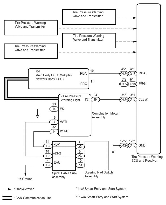
CAUTION / NOTICE / HINT
- NOTICE:
- ·
When replacing the tire pressure warning ECU and receiver or tire pressure warning valve and transmitter, read the transmitter IDs and number of the transmitters (4 or 5) stored in the old ECU using the GTS and write them down before removal.
·It is necessary to perform initializationSuspension>TIRE PRESSURE MONITORING>TIRE PRESSURE WARNING SYSTEM (for Gasoline Model (for Type A))>INITIALIZATION202304,999999,_53,_080780,_0393955,RM100000002BB37, after registrationSuspension>TIRE PRESSURE MONITORING>TIRE PRESSURE WARNING SYSTEM (for Gasoline Model (for Type A))>REGISTRATION202304,999999,_53,_080780,_0393955,RM100000002B0BZ, of the transmitter IDs into the tire pressure warning ECU and receiver if the ECU and/or one of the valve and transmitters has been replaced.
PROCEDURE
Check that the following conditions are not met:
Facilities or devices that use similar radio frequencies are located in the vicinity of the vehicle.
- HINT:
-
If the vehicle is located in an area such as the one described above, the tire pressure warning light may blink due to interfering radio frequencies.
Devices using similar radio frequencies are used in the vehicle.
- HINT:
-
Radio transmissions may be interrupted due to the surroundings or devices installed by the user.
- Result:
Result Proceed to There is no device or facility that uses electrical waves of approximately the same frequency in the vicinity of the vehicle or inside the vehicle. A There is a device or facility that uses electrical waves of approximately the same frequency in the vicinity of the vehicle or inside the vehicle. B
A
B
Check the stored DTC.
- Result:
Result Proceed to Any DTCs from C2121 to C2124 are output (C2181 to C2184 when in Test Mode) A All DTCs from C2121 to C2124 are output (C2181 to C2184 when in Test Mode) B
A
B
Turn the ignition switch off.
Connect the GTS to the DLC3.
Turn the ignition switch to ON.
Turn the GTS on.
Enter the following menus: Chassis / Tire Pressure Monitor / Data List.
Display the "ID Tire Position" value for each wheel using the GTS.
Refer to the following chart and check the wheel position of the DTC and transmitter match.
- Chassis > Tire Pressure Monitor > Data List
-
Tester Display Measurement Item Range Normal Condition Diagnostic Note ID 1 Tire Position ID1 Tire Position No Information or FL or FR or RL or RR or Spare or Judging ID1 tire position is displayed If no tire position information is stored, "No Information" will be displayed. ID 2 Tire Position ID2 Tire Position No Information or FL or FR or RL or RR or Spare or Judging ID2 tire position is displayed If no tire position information is stored, "No Information" will be displayed. ID 3 Tire Position ID3 Tire Position No Information or FL or FR or RL or RR or Spare or Judging ID3 tire position is displayed If no tire position information is stored, "No Information" will be displayed. ID 4 Tire Position ID4 Tire Position No Information or FL or FR or RL or RR or Spare or Judging ID4 tire position is displayed If no tire position information is stored, "No Information" will be displayed.
- HINT:
-
Refer to the following chart for the Data List items that correspond to the DTCs.
DTC No. Detection Item Data List C2121 Transmitter ID 1 not Received (Main) ID1 Tire Position C2181 Transmitter ID 1 not Received (for Test Diagnosis) C2122 Transmitter ID 2 not Received (Main) ID2 Tire Position C2182 Transmitter ID 2 not Received (for Test Diagnosis) C2123 Transmitter ID 3 not Received (Main) ID3 Tire Position C2183 Transmitter ID 3 not Received (for Test Diagnosis) C2124 Transmitter ID 4 not Received (Main) ID4 Tire Position C2184 Transmitter ID 4 not Received (for Test Diagnosis)
- Chassis > Tire Pressure Monitor > Data List
-
Tester Display ID 1 Tire Position ID 2 Tire Position ID 3 Tire Position ID 4 Tire Position - 50003 203 78,54,55,56
- Result:
Proceed to NEXT
NEXT
Turn the ignition switch off.
Connect the GTS to the DLC3.
Turn the ignition switch to ON.
Turn the GTS on.
Enter the following menus: Chassis / Tire Pressure Monitor / Data List.
Refer to the following chart and record the tire pressure warning valve and transmitter ID of the output DTC.
- Chassis > Tire Pressure Monitor > Data List
-
Tester Display Measurement Item Range Normal Condition Diagnostic Note Registered ID 1 Code Registered ID1 code min.: 0
max.: FFFFFFF*1ID No. registered for transmitter ID1 displayed - Registered ID 2 Code Registered ID2 code min.: 0
max.: FFFFFFF*1ID No. registered for transmitter ID2 displayed - Registered ID 3 Code Registered ID3 code min.: 0
max.: FFFFFFF*1ID No. registered for transmitter ID3 displayed - Registered ID 4 Code Registered ID4 code min.: 0
max.: FFFFFFF*1ID No. registered for transmitter ID4 displayed -
- HINT:
- ·
*1: Displayed only when the ID No. is not registered.
·Refer to the following chart for the Data List items that correspond to the DTCs.
DTC No. Detection Item Data List C2121 Transmitter ID 1 not Received (Main) Registered ID 1 code C2181 Transmitter ID 1 not Received (for Test Diagnosis) C2122 Transmitter ID 2 not Received (Main) Registered ID 2 code C2182 Transmitter ID 2 not Received (for Test Diagnosis) C2123 Transmitter ID 3 not Received (Main) Registered ID 3 code C2183 Transmitter ID 3 not Received (for Test Diagnosis) C2124 Transmitter ID 4 not Received (Main) Registered ID 4 code C2184 Transmitter ID 4 not Received (for Test Diagnosis)
- Chassis > Tire Pressure Monitor > Data List
-
Tester Display Registered ID 1 Code Registered ID 2 Code Registered ID 3 Code Registered ID 4 Code - 50003 203 7,8,9,10
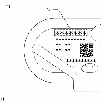
| *1 | Tire Pressure Warning Valve and Transmitter |
| *a | Transmitter ID (7-digit Number) |
Disassemble the tire indicated in the output DTC and check the tire pressure warning valve and transmitter ID.
Confirm that the ID number on the transmitter and recorded transmitter ID match.
- Result:
Result Proceed to Match A Do not match B
A
B
Perform a test mode inspection and perform Transmitter Data Reception Check (C2181 to C2184).
- Result:
Proceed to OK NG
OK
Explain to the customer that there is a high possibility that a DTC was output due to temporary electrical wave interference.
NG
Turn the ignition switch off.
Connect the GTS to the DLC3.
Turn the ignition switch to ON.
Turn the GTS on.
Enter the following menus: Chassis / Tire Pressure Monitor / Data List.
Refer to the following chart and record all of the tire pressure warning valve and transmitter IDs.
- Chassis > Tire Pressure Monitor > Data List
-
Tester Display Measurement Item Range Normal Condition Diagnostic Note Registered ID 1 Code Registered ID1 code min.: 0
max.: FFFFFFF*1ID No. registered for transmitter ID1 displayed - Registered ID 2 Code Registered ID2 code min.: 0
max.: FFFFFFF*1ID No. registered for transmitter ID2 displayed - Registered ID 3 Code Registered ID3 code min.: 0
max.: FFFFFFF*1ID No. registered for transmitter ID3 displayed - Registered ID 4 Code Registered ID4 code min.: 0
max.: FFFFFFF*1ID No. registered for transmitter ID4 displayed -
- HINT:
- ·
*1: Displayed only when the ID No. is not registered.
·The wheel position cannot be determined from ID1 through ID4 on the Data List.
- Chassis > Tire Pressure Monitor > Data List
-
Tester Display Registered ID 1 Code Registered ID 2 Code Registered ID 3 Code Registered ID 4 Code - 50003 203 7,8,9,10
| *1 | Tire Pressure Warning Valve and Transmitter |
| *a | Transmitter ID (7-digit Number) |
Disassemble all of the tires and check the tire pressure warning valve and transmitter IDs.
Confirm that the ID number on the transmitter and recorded transmitter ID match.
- Result:
Result Proceed to Match A Do not match B
A
B
- Result:
Proceed to NEXT
NEXT
- Result:
Proceed to NEXT
NEXT
Clear the DTCs.
- Chassis > Tire Pressure Monitor > Clear DTCs
- 50002 203
- Result:
Proceed to NEXT
NEXT
Clear the DTCs.
- Chassis > Tire Pressure Monitor > Clear DTCs
- 50002 203
- Result:
Proceed to NEXT
NEXT
Explain to the customer that there is a high possibility that a device (located near or inside the vehicle) or facility using electrical waves of approximately the same frequency is causing electrical wave interference.