SLIDING ROOF / CONVERTIBLE SLIDING ROOF SYSTEM(for NR Series Engine) Sliding Roof does not Move by Operating Sliding Roof Control Switch
DESCRIPTION
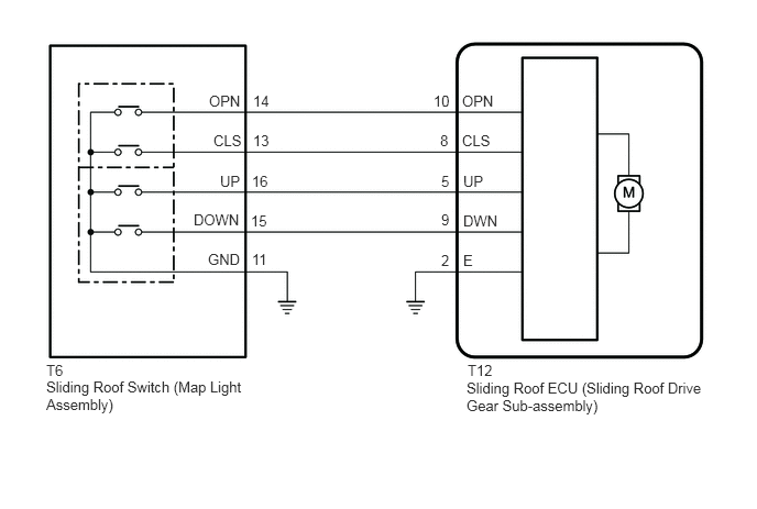
The sliding roof ECU (sliding roof drive gear sub-assembly) receives slide and tilt signals and operates its built-in motor when the sliding roof switch (map light assembly) is operated.
WIRING DIAGRAM
CAUTION / NOTICE / HINT
- NOTICE:
- ·
If the sliding roof ECU (sliding roof drive gear sub-assembly) is removed and reinstalled or replaced, the sliding roof ECU (sliding roof drive gear sub-assembly) must be initialized.
·If a sliding roof ECU (sliding roof drive gear sub-assembly) DTC is output, first perform troubleshooting for the sliding roof ECU (sliding roof drive gear sub-assembly) DTC.
PROCEDURE
Connect the GTS to the DLC3.
Turn the engine switch on (IG).
Turn the GTS on.
Enter the following menus: Body Electrical / Sliding Roof / Active Test.
Perform the Active Test according to the display on the GTS.
- Body Electrical > Sliding Roof > Active Test
-
Tester Display Measurement Item Control Range Diagnostic Note Slide Roof Operate sliding roof motor OFF / Opn/Dwn / Clos/Up -
- Body Electrical > Sliding Roof > Active Test
-
Tester Display Slide Roof - 50004 147 1
- OK:
Slide roof is operated using GTS.
- Result:
Proceed to OK NG
OK
NG
Enter the following menus: Body Electrical / Sliding Roof / Data List.
Read the Data List according to the display on the GTS.
- Body Electrical > Sliding Roof > Data List
-
Tester Display Measurement Item Range Normal Condition Diagnostic Note Open Switch OPEN switch signal OFF or ON OFF: OPEN switch not pressed
ON: OPEN switch pressed- Close Switch CLOSE switch signal OFF or ON OFF: CLOSE switch not pressed
ON: CLOSE switch pressed- Up Switch UP switch signal OFF or ON OFF: UP switch not pressed
ON: UP switch pressed- Down Switch DOWN switch signal OFF or ON OFF: DOWN switch not pressed
ON: DOWN switch pressed-
- Body Electrical > Sliding Roof > Data List
-
Tester Display Open Switch Close Switch Up Switch Down Switch - 50003 147 1,4,7,10
- OK:
The GTS display changes according to the operation of each switch as shown in the table.
- Result:
Proceed to OK NG
OK
NG
Remove the sliding roof switch (map light assembly).
Inspect the sliding roof switch (map light assembly).
- Result:
Proceed to OK NG
OK
NG
Disconnect the T6 sliding roof switch (map light assembly) connector.
Disconnect the T12 sliding roof ECU (sliding roof drive gear sub-assembly) connector.
Measure the resistance according to the value(s) in the table below.
- Standard Resistance:
Tester Connection Condition Specified Condition T12-8 (CLS) - T6-13 (CLS) Always Below 1 Ω T12-8 (CLS) or T6-13 (CLS) - Body ground Always 10 kΩ or higher T12-10 (OPN) - T6-14 (OPN) Always Below 1 Ω T12-10 (OPN) or T6-14 (OPN) - Body ground Always 10 kΩ or higher T12-9 (DWN) - T6-15 (DOWN) Always Below 1 Ω T12-9 (DWN) or T6-15 (DOWN) - Body ground Always 10 kΩ or higher T12-5 (UP) - T6-16 (UP) Always Below 1 Ω T12-5 (UP) or T6-16 (UP) - Body ground Always 10 kΩ or higher T6-11 (GND) - Body ground Always Below 1 Ω T12-2 (E) - Body ground Always Below 1 Ω
- Result:
Proceed to OK NG
OK
NG
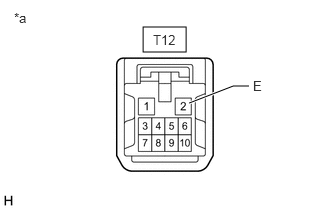
| *a | Front view of wire harness connector
(to Sliding Roof ECU (Sliding Roof Drive Gear Sub-assembly)) |
Disconnect the T12 sliding roof ECU (sliding roof drive gear sub-assembly) connector.
Measure the resistance according to the value(s) in the table below.
- Standard Resistance:
Tester Connection Condition Specified Condition T12-2 (E) - Body ground Always Below 1 Ω
- Result:
Proceed to OK NG
OK
NG