TELEMATICS TELEMATICS SYSTEM(for Gasoline Model) Remote Engine Starter does not Operate
WIRING DIAGRAM
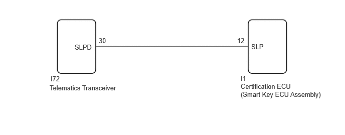
CAUTION / NOTICE / HINT
- NOTICE:
- ·
Depending on the parts that are replaced during vehicle inspection or maintenance, performing initialization, registration or calibration may be needed. Refer to Registration for Telematics System.
·Before replacing the telematics transceiver, refer to Service Bulletin.
PROCEDURE
Check that the engine can be started by pressing the engine switch.
- Result:
Result Proceed to Engine can be started. A Engine cannot be started. B
A
B
except NR Series: Click hereVehicle Interior>THEFT DETERRENT / KEYLESS ENTRY>SMART ENTRY AND START SYSTEM (for Start Function, Gasoline Model (except NR Series))>HOW TO PROCEED WITH TROUBLESHOOTING202304,999999,_58,_080747,_0600574,RM100000002BD88,
for NR Series: Click hereVehicle Interior>THEFT DETERRENT / KEYLESS ENTRY>SMART ENTRY AND START SYSTEM (for Start Function, Gasoline Model (NR Series))>HOW TO PROCEED WITH TROUBLESHOOTING202304,999999,_58,_080747,_0586354,RM1000000029OG1,
- HINT:
- If registration is not performed after replacing any of the following parts, the remote engine start and stop will not be available.·
Certification ECU (smart key ECU assembly)
·telematics transceiver
Perform remote engine start and stop registration.
- HINT:
-
Refer to Service Bulletin.
Check if the problem symptom recurs.
- Result:
Result Proceed to System does not return to normal. A System returns to normal. B
A
B
Choose the model to be inspected.
- Result:
Result Proceed to for 10.25 Inch Display with Remote Engine Starter A except 10.25 Inch Display with Remote Engine Starter B
A
B
Clear the DTCs.
- Body Electrical > Power Source Control > Clear DTCs
- 50002 223
Check for DTCs.
- Body Electrical > Power Source Control > Trouble Codes
- 50001 223
- Result:
Result Proceed to DTC B2285 is not output. A DTC B2285 is output. B
A
B

| *a | Front view of harness connector
(to Telematics Transceiver) |
Disconnect the telematics transceiver connector.
Measure the voltage according to the value(s) in the table below.
- Standard Voltage:
Tester Connection Condition Specified Condition I72-30 (SLPD) - Body ground Steering locked 11 to 14 V Steering unlocked Below 1.5 V
- HINT:
-
The steering locks when any door is opened with the shift lever in P and the engine switch off. The steering unlocks when the engine switch is turned on (IG).
- Result:
Proceed to OK NG
OK
NG
Disconnect the I72 telematics transceiver connector.
Disconnect the I1 certification ECU (smart key ECU assembly) connector.
Measure the resistance according to the value(s) in the table below.
- Standard Resistance:
Tester Connection Condition Specified Condition I72-30 (SLPD) - I1-12 (SLP) Always Below 1 Ω
- Result:
Proceed to OK NG
OK
NG