METER / GAUGE / DISPLAY METER / GAUGE SYSTEM(for 12.3 Inch Display) Odo/Trip Switch Malfunction
DESCRIPTION
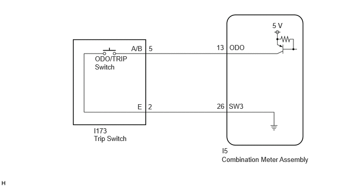
The trip switch is connected to the combination meter assembly via direct line. When the ODO/TRIP switch is operated, the display of the multi-information display changes or the displayed value is reset.
WIRING DIAGRAM
for GTMC Made
for TFTM Made
CAUTION / NOTICE / HINT
- NOTICE:
- ·
When replacing the combination meter assembly, always replace it with a new one. If a combination meter assembly which was installed to another vehicle is used, the information stored in it will not match the information from the vehicle and a DTC may be stored.
·When replacing the combination meter assembly, update the ECU security key.
PROCEDURE
Perform the Active Test according to the display on the GTS.
- Body Electrical > Combination Meter > Active Test
-
Tester Display Measurement Item Control Range Diagnostic Note ODO/TRIP Change Switch Performs the same operation as pressing the ODO/TRIP switch OFF/ON -
- Body Electrical > Combination Meter > Active Test
-
Tester Display ODO/TRIP Change Switch - 50004 409 190
- Result:
Result Proceed to Active Test can be performed correctly A Active Test cannot be performed correctly B
A
B
Read the Data List according to the display on the GTS.
- Body Electrical > Combination Meter > Data List
-
Tester Display Measurement Item Range Normal Condition Diagnostic Note ODO/TRIP Change Switch ODO/TRIP switch operation OFF or ON OFF: Switch released
ON: Switch pushed-
- Body Electrical > Combination Meter > Data List
-
Tester Display ODO/TRIP Change Switch - 50003 409 2
- Result:
Result Proceed to The value of the Data List item is correct, and the combination meter assembly operates correctly A The value of the Data List item is correct, but the combination meter assembly does not operate correctly B The Data List item changes correctly C
A
B
C
- Result:
Proceed to OK NG
OK
NG
Choose the model to be inspected.
- Result:
Result Proceed to for GTMC Made A for TFTM Made B
A
B
Disconnect the I5 combination meter assembly connector.
Measure the resistance according to the value(s) in the table below.
- Standard Resistance:
Tester Connection Condition Specified Condition I173-5 (A/B) - I5-13 (ODO) Always Below 1 Ω I173-2 (E) - I5-26 (SW3) Always Below 1 Ω I173-5 (A/B) or I5-13 (ODO) - Body ground Always 10 kΩ or higher
- Result:
Proceed to OK NG
OK
NG
Disconnect the I5 combination meter assembly connector.
Measure the resistance according to the value(s) in the table below.
- Standard Resistance:
Tester Connection Condition Specified Condition I198-5 (A/B) - I5-13 (ODO) Always Below 1 Ω I198-2 (E) - I5-26 (SW3) Always Below 1 Ω I198-5 (A/B) or I5-13 (ODO) - Body ground Always 10 kΩ or higher
- Result:
Proceed to OK NG
OK
NG