HEATING / AIR CONDITIONING AIR CONDITIONING SYSTEM(for Gasoline Model (NR Series) with Manual Air Conditioning System for Mechanical Control Type) Ambient Temperature Display System
DESCRIPTION
The thermistor assembly is installed in front of the cooler condenser assembly to detect the ambient temperature, which is used to control the air conditioning system. The thermistor assembly detects fluctuations in the ambient temperature and sends it as a signal to the combination meter assembly. This data is used for controlling the cabin temperature. The resistance of the thermistor assembly changes in accordance with the ambient temperature. As the temperature decreases, the resistance increases. As the temperature increases, the resistance decreases. The combination meter assembly applies voltage (5 V) to the thermistor assembly and detects voltage changes due to changes in the resistance of the thermistor assembly.
- NOTICE:
-
The thermistor assembly detects the ambient temperature in its vicinity, not the ambient temperature around the vehicle. Depending on factors such as radiant heat from the engine room and the vehicle speed, the ambient temperature detected by the thermistor assembly may differ from the ambient temperature displayed on the multi-information display in the combination meter assembly. For example:
- ·
When the vehicle is stopped or being driven at low speeds, the displayed ambient temperature will not be updated to a higher temperature to adjust for and minimize the influence of radiant heat from the engine room on the air conditioning system control. When the vehicle is not being driven at low speeds, the adjustment is performed, but updating of the displayed ambient temperature to a higher temperature is delayed. The displayed ambient temperature will be updated to a lower temperature regardless of the vehicle speed.
·When the ambient temperature around the thermistor assembly suddenly changes due to any reason other than radiant heat from the engine room, such as when the vehicle enters or exits a garage or tunnel, the actual ambient temperature of the vehicle and the displayed ambient temperature may differ or changing of the displayed value may be delayed.
WIRING DIAGRAM
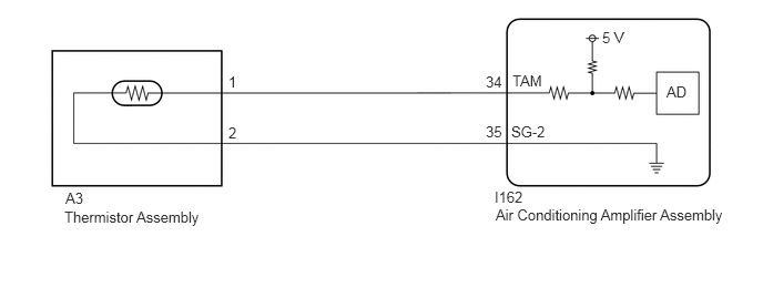
CAUTION / NOTICE / HINT
- NOTICE:
- ·
After the ignition switch is turned off, there may be a waiting time before disconnecting the negative (-) battery terminal.
- HINT:
-
When disconnecting and reconnecting the battery, there is an automatic learning function that completes learning when the respective system is used.
·Before starting the inspection, it is necessary to release the residual heat from the engine room (engine unit and coolant hoses, etc.) after stopping the engine and electric motor (when the vehicle is parked after being driven). Therefore, move and park the vehicle in the following type of temperature measurement location.
-A location within the vehicle service area which has a relatively low amount of environmental temperature changes in the area surrounding the vehicle.
-A location with a level surface made of a material such as concrete which transmits a relatively low amount of heat from the ground, such as concrete.
-A location with no heat influences around the vehicle to be inspected such as other vehicles with a running engine and electric motors, exhaust gas ducts installed on the exhaust pipes, stoves, etc.
·The air conditioning system uses the CAN communication system. Inspect the communication function by following How to Proceed with Troubleshooting. Troubleshoot the air conditioning system after confirming that the communication system is functioning properly.
·Ignition switch operation during parked vehicle inspection:
Turn the ignition switch to ON. (Do not start the engine and electric motor.)
PROCEDURE
Connect the GTS to the DLC3.
Turn the ignition switch to ON.
Turn the GTS on.
Enter the following menus: Body Electrical / Air Conditioner / Trouble Codes.
Check for DTCs.
- Body Electrical > Air Conditioner > Trouble Codes
- 50001 121
- Result:
Result Proceed to B1412 is not output A B1412 is output B
A
B
Remove the thermistor assembly.
Inspect the thermistor assembly.
- Result:
Proceed to OK NG
OK
NG
- NOTICE:
-
During the parked vehicle inspection, perform the inspection with the ignition switch off (do not start the engine and electric motor).
Disconnect the I162 air conditioning amplifier assembly connector.
Measure the resistance according to the value(s) in the table below.
- Standard Resistance:
Tester Connection Condition Specified Condition A3-1 - I162-34 (TAM) Always Below 1 Ω A3-2 - I162-35 (SG-2) Always Below 1 Ω A3-1 or I162-34 (TAM) - Other terminals and body ground Always 10 kΩ or higher A3-2 or I162-35 (SG-2) - Other terminals and body ground Always 10 kΩ or higher
- Result:
Proceed to OK NG
OK
NG
Disconnect the cable from the negative (-) battery terminal and wait for at least 90 seconds.
- NOTICE:
-
Make sure the wire harness(es) and connector(s) for the vehicle being inspected are connected. After the ignition switch is turned off, the navigation system stores the various memory and settings within approximately 6 minutes. Therefore, make sure to disconnect the cable from the negative (-) battery terminal after confirming that 6 minutes or more have elapsed since turning the ignition switch off.
- HINT:
-
The air conditioning amplifier assembly reads and memorizes the thermistor assembly (ambient temperature sensor) detection value (THO) from before the ignition switch was turned off for 1 hour after turning the ignition switch off. Therefore, it is necessary to switch off the air conditioning amplifier assembly internal power source and clear the stored values from before the ignition switch was turned off.
Connect the cable to the negative (-) battery terminal.
Measure and make a note of the ambient temperature near the thermistor assembly using a thermometer.
- NOTICE:
- ·
Perform the following procedure with the ignition switch ON.
·Wait at least 6 minutes for the values of the thermistor assembly and thermometer to become stable before taking a measurement.
·Hold the thermometer 50 mm (1.97 in.) from the thermistor assembly with its sensing portion at the same height and perpendicular to the thermistor assembly.
·Hold the sensor only by its connector. Touching the sensing portion may change the resistance value.
·When measuring the ambient temperature with a thermometer, do not move the thermometer, touch the sensing portion or allow it to contact the vehicle body.
Make a note of the ambient temperature displayed on the multi-information display in the combination meter assembly.
Compare the value of the ambient temperature measured by the thermometer and the thermistor assembly.
- OK:
The value of the ambient temperature measured by the thermometer and the thermistor assembly are almost the same.
- Result:
Proceed to OK NG
OK
NG