HEATING / AIR CONDITIONING AIR CONDITIONING SYSTEM(for Gasoline Model (NR Series) with Manual Air Conditioning System for Electrical Control Type) B1497 Communication Malfunction (Bus Ic)
DESCRIPTION
The air conditioning harness assembly connects the air conditioning amplifier assembly and the servo motors. The air conditioning amplifier assembly supplies power and sends operation instructions to each servo motor through the air conditioning harness assembly. Each servo motor sends damper position information to the air conditioning amplifier assembly.
| DTC No. | Detection Item | DTC Detection Condition | Trouble Area | Memory |
|---|---|---|---|---|
| B1497 | Communication Malfunction (Bus Ic) | Error or open in communication line | ·
Air conditioning harness assembly ·
No. 1 air conditioning radiator damper servo sub-assembly ·
Air conditioning amplifier assembly |
Memorized
(10 sec. or more)* |
*: The air conditioning amplifier assembly stores this DTC if the malfunction has occurred for the period of time indicated in the brackets.
WIRING DIAGRAM
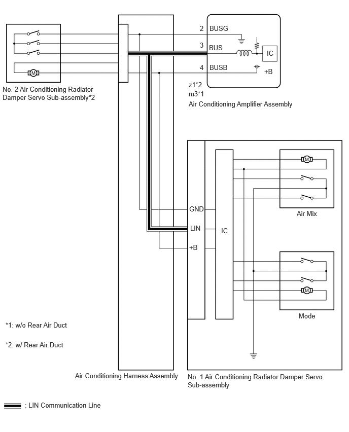
PROCEDURE
Choose the model to be inspected.
- Result:
Result Proceed to w/ Rear Air Duct A w/o Rear Air Duct B
A
B
Connect the GTS to the DLC3.
Turn the ignition switch to ON.
Turn the GTS on.
Enter the following menus: Body Electrical / Air Conditioner / Active test.
Perform the Active Test according to the display on the GTS.
- Body Electrical > Air Conditioner > Active Test
-
Tester Display Measurement Item Control Range Diagnostic Note Air Outlet Servo Pulse (D) No. 1 air conditioning radiator damper servo sub-assembly pulse Min.: 128
Max.: 383Operates between 241 and 348 pulses A/O Servo Pulse(Rr D) No. 2 air conditioning radiator damper servo sub-assembly pulse Min.: 128
Max.: 383Operates between 250 and 297 pulses
- Body Electrical > Air Conditioner > Active Test
-
Tester Display Air Outlet Servo Pulse (D) - 50004 121 26
- Body Electrical > Air Conditioner > Active Test
-
Tester Display A/O Servo Pulse(Rr D) - 50004 121 56
- Result:
Result Proceed to All of the damper servo motors are malfunctioning A One of the damper servo motors is malfunctioning B
A
B
Disconnect the No. 1 air conditioning radiator damper servo sub-assembly connector.
Connect the GTS to the DLC3.
Turn the ignition switch to ON.
Turn the GTS on.
Enter the following menus: Body Electrical / Air Conditioner / Active test.
Perform the Active Test according to the display on the GTS.
- Body Electrical > Air Conditioner > Active Test
-
Tester Display Measurement Item Control Range Diagnostic Note A/O Servo Pulse(Rr D) No. 2 air conditioning radiator damper servo sub-assembly pulse Min.: 128
Max.: 383Operates between 250 and 297 pulses
- Body Electrical > Air Conditioner > Active Test
-
Tester Display A/O Servo Pulse(Rr D) - 50004 121 56
- OK:
The damper servo motor operates smoothly.
- Result:
Proceed to OK NG
OK
NG
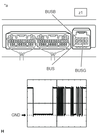
| *a | Component with harness connected
(Air Conditioning Amplifier Assembly) |
- NOTICE:
-
When inspecting the air conditioning amplifier assembly, do not bring the tester probes too close to each other as a short circuit may occur.
Disconnect the z1 air conditioning amplifier assembly connector.
Measure the resistance according to the value(s) in the table below.
- Standard Resistance:
Tester Connection Condition Specified Condition z1-2 (BUSG) - Body ground Always Below 1 Ω
Measure the voltage according to the value(s) in the table below.
- Standard Voltage:
Tester Connection Condition Specified Condition z1-4 (BUSB) - Body ground Ignition switch ON 11 to 14 V
Turn the ignition switch to ON.
Using an oscilloscope, check the waveform.
| Item | Content |
|---|---|
| Terminal No. | z1-3 (BUS) - z1-2 (BUSG) |
| Tool Setting | 2 V/DIV., 2 ms./DIV. |
| Condition | Ignition switch ON |
- OK:
Waveform is similar to that shown in the illustration.
- HINT:
-
The waveform varies with the blower speed.
- Result:
Proceed to OK NG
OK
NG
Connect the GTS to the DLC3.
Turn the ignition switch to ON.
Turn the GTS on.
Enter the following menus: Body Electrical / Air Conditioner / Active test.
Perform the Active Test according to the display on the GTS.
- Body Electrical > Air Conditioner > Active Test
-
Tester Display Measurement Item Control Range Diagnostic Note Air Outlet Servo Pulse (D) No. 1 air conditioning radiator damper servo sub-assembly pulse Min.: 128
Max.: 383Operates between 241 and 348 pulses A/O Servo Pulse(Rr D) No. 2 air conditioning radiator damper servo sub-assembly pulse Min.: 128
Max.: 383Operates between 250 and 297 pulses
- Body Electrical > Air Conditioner > Active Test
-
Tester Display Air Outlet Servo Pulse (D) - 50004 121 26
- Body Electrical > Air Conditioner > Active Test
-
Tester Display A/O Servo Pulse(Rr D) - 50004 121 56
- Result:
Result Proceed to Only the No. 2 air conditioning radiator damper servo sub-assembly operates A Only the No. 1 air conditioning radiator damper servo sub-assembly operate B
A
B
Disconnect the z1 air conditioning amplifier assembly connector.
Disconnect the No. 1 air conditioning radiator damper servo sub-assembly connector.
Measure the resistance according to the value(s) in the table below.
- Standard Resistance:
Tester Connection Condition Specified Condition z1-2 (BUSG) - A-3 (GND) Always Below 1 Ω z1-3 (BUS) - A-2 (LIN) Always Below 1 Ω z1-4 (BUSB) - A-1 (+B) Always Below 1 Ω
- Result:
Proceed to OK NG
OK
NG
Connect the GTS to the DLC3.
Turn the ignition switch to ON.
Turn the GTS on.
Enter the following menus: Body Electrical / Air Conditioner / Active test.
Perform the Active Test according to the display on the GTS.
- Body Electrical > Air Conditioner > Active Test
-
Tester Display Measurement Item Control Range Diagnostic Note Air Outlet Servo Pulse (D) No. 1 air conditioning radiator damper servo sub-assembly pulse Min.: 128
Max.: 383Operates between 241 and 348 pulses
- Body Electrical > Air Conditioner > Active Test
-
Tester Display Air Outlet Servo Pulse (D) - 50004 121 26
- OK:
The damper servo motor operates smoothly.
- Result:
Proceed to OK NG
OK
NG
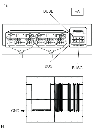
| *a | Component with harness connected
(Air Conditioning Amplifier Assembly) |
- NOTICE:
-
When inspecting the air conditioning amplifier assembly, do not bring the tester probes too close to each other as a short circuit may occur.
Disconnect the m3 air conditioning amplifier assembly connector.
Measure the resistance according to the value(s) in the table below.
- Standard Resistance:
Tester Connection Condition Specified Condition m3-2 (BUSG) - Body ground Always Below 1 Ω
Measure the voltage according to the value(s) in the table below.
- Standard Voltage:
Tester Connection Condition Specified Condition m3-4 (BUSB) - Body ground Ignition switch ON 11 to 14 V
Turn the ignition switch to ON.
Using an oscilloscope, check the waveform.
| Item | Content |
|---|---|
| Terminal No. | m3-3 (BUS) - m3-2 (BUSG) |
| Tool Setting | 2 V/DIV., 2 ms./DIV. |
| Condition | Ignition switch ON |
- OK:
Waveform is similar to that shown in the illustration.
- HINT:
-
The waveform varies with the blower speed.
- Result:
Proceed to OK NG
OK
NG