☰ Toyota Levin Turbo☰ فهرستVehicle Interior › HEATING / AIR CONDITIONING › AIR CONDITIONING SYSTEM(for Gasoline Model (NR Series) with Manual Air Conditioning System for Electrical Control Type)
RM3660EC
_58
Vehicle Interior
_080733
HEATING / AIR CONDITIONING
_0591215
AIR CONDITIONING SYSTEM(for Gasoline Model (NR Series) with Manual Air Conditioning System for Electrical Control Type)
C
HEATING / AIR CONDITIONING AIR CONDITIONING SYSTEM(for Gasoline Model (NR Series) with Manual Air Conditioning System for Electrical Control Type) B1451 Compressor Solenoid Circuit
DESCRIPTION
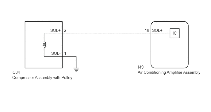
In this circuit, the compressor assembly with pulley receives refrigerant compression demand signals from the air conditioning amplifier assembly.
Based on this signal, the compressor assembly with pulley changes the amount of compressor output.
| DTC No. | Detection Item | DTC Detection Condition | Trouble Area | Memory |
|---|---|---|---|---|
| B1451 | Compressor Solenoid Circuit | Open or short in compressor solenoid circuit | ·
Compressor assembly with pulley ·
Harness or connector ·
Air conditioning amplifier assembly |
- |
WIRING DIAGRAM
1.708,0.948 2.177,1.146
0.469,0.198
10
false
SOL+
2.177,0.948 2.375,1.146
0.198,0.198
10
false
2
1.74,1.729 2.208,1.927
0.469,0.198
10
false
SOL-
2.177,1.729 2.375,1.927
0.198,0.198
10
false
1
0.427,2.375 1.573,2.583
1.146,0.208
10
false
C84
0.417,2.552 2.583,2.771
2.167,0.219
10
false
Compressor Assembly with Pulley
4.917,0.948 5.177,1.156
0.26,0.208
10
false
18
5.167,0.948 5.635,1.146
0.469,0.198
10
false
SOL+
5.865,1.042 6.083,1.24
0.219,0.198
10
false
IC
4.677,2.375 6.896,2.594
2.219,0.219
10
false
Air Conditioning Amplifier Assembly
4.688,2.198 4.99,2.406
0.302,0.208
10
false
I49
PROCEDURE
1.CHECK HARNESS AND CONNECTOR (COMPRESSOR ASSEMBLY WITH PULLEY - AIR CONDITIONING AMPLIFIER ASSEMBLY)
a.
Disconnect the I49 air conditioning amplifier assembly connector.
b.
Measure the resistance according to the value(s) in the table below.
- Standard Resistance:
Tester Connection Condition Specified Condition C84-2 (SOL+) - I49-18 (SOL+) Always Below 1 Ω C84-2 (SOL+) or I49-18 (SOL+) - Other terminals and body ground Always 10 kΩ or higher
- Result:
Proceed to OK NG
OK
2.INSPECT AIR CONDITIONING AMPLIFIER ASSEMBLY
NG
REPAIR OR REPLACE HARNESS OR CONNECTOR
2.INSPECT AIR CONDITIONING AMPLIFIER ASSEMBLY
1.469,0.281 1.927,0.51
0.458,0.229
2.323,1.823 1.896,1.313
true
1.573,0.323 2,0.563
0.427,0.24
10
false
C84
3.042,3.406 3.385,3.594
0.344,0.188
10
false
GND
2.25,1.865 2.813,2.073
0.563,0.208
10
false
SOL+
0.115,0.104 0.49,0.344
0.375,0.24
12
false
*a
| *a | Front view of wire harness connector
(to Compressor Assembly with Pulley) |
a.
Disconnect the C84 compressor assembly with pulley connector.
b.
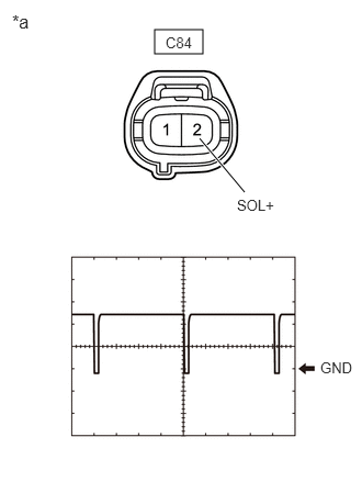
Check the waveform.
| Item | Content |
|---|---|
| Terminal No. | C84-2 (SOL+) - Body ground |
| Tool Setting | 5 V/DIV., 500 μs./DIV. |
| Condition | ·
Engine running ·
Blower switch: LO ·
A/C switch: On |
- OK:
Waveform is similar to that shown in the illustration.
- Result:
Proceed to OK NG
OK
REPLACE COMPRESSOR ASSEMBLY WITH PULLEY
NG
REPLACE AIR CONDITIONING AMPLIFIER ASSEMBLY