THEFT DETERRENT / KEYLESS ENTRY THEFT DETERRENT SYSTEM(for NR Series Engine) Improper Operation
DESCRIPTION
If the alarm function of the theft deterrent system operates unintentionally, one of the following may be the cause.
Short to ground in any door courtesy light switch circuit or the engine hood courtesy switch (hood lock assembly) circuit.
Unstable main body ECU (multiplex network body ECU) power source voltage.
- HINT:
-
Preconditions for arming preparation:
Make sure the engine switch is off, all the doors and the hood are closed and all the doors have been locked by wireless operation or entry operation.
WIRING DIAGRAM
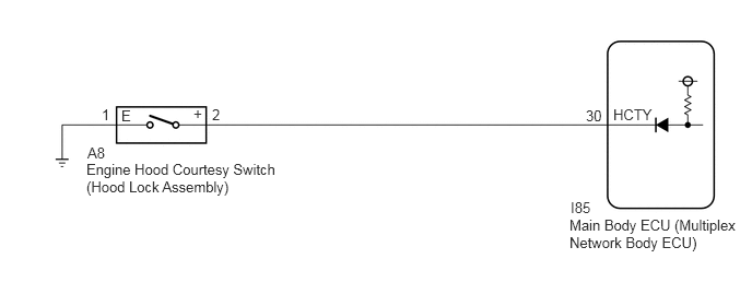
CAUTION / NOTICE / HINT
- NOTICE:
- ·
Before replacing the main body ECU (multiplex network body ECU), refer to Service Bulletin.
·The theft deterrent system uses the CAN communication system. Inspect the communication function by following How to Proceed with Troubleshooting. Troubleshoot the theft deterrent system after confirming that the communication system is functioning properly.
·The following troubleshooting procedure is based on the assumption that systems related to the theft deterrent system are normal. Confirm that the systems related to the theft deterrent system are not malfunctioning before performing the following procedure.
·If the vehicle or vehicle controls are operated (for example, during initial inspection when the vehicle is brought in for repair) before operation history has been read and saved, the operation history information could be lost.
·The operation history function uses the current system time of the GTS and the time counter inside the controlling ECU to calculate the times shown in the operation history. For this reason, before reading the operation history, first make sure that the GTS system clock is accurately set to the current time.
PROCEDURE
Use the GTS to check the theft deterrent system operation history around the time the customer reported the malfunction to have occurred.
Check if there is operation history around the time that the customer reported the malfunction to have occurred, and perform an operation check.
- Result:
Result Proceed to There is operation history around the time that the customer reported the malfunction to have occurred, but a malfunction could not be identified during the operation check. A There is operation history around the time that the customer reported the malfunction to have occurred, and the malfunction was identified during the operation check. B There is no operation history around the time that the customer reported the malfunction to have occurred. C
A
B
C
Check that the security indicator light is illuminated when the theft deterrent system is in the arming preparation state.
Check that the security indicator light blinks when the theft deterrent system is in the arming state.
- HINT:
State of Theft Deterrent System Contents Security Indicator Light Condition Disarmed state (1), (2) Theft deterrent system is unset. ·Off (Immobiliser function unset)
·Blinking (Immobiliser function set)
Arming preparation state Standby period after theft deterrent system set conditions are met but before theft deterrent system is actually set (approximately 9 seconds).
(Theft detection not possible)On Armed state Theft deterrent system is set.
(Theft detection is possible)Blinking (Immobiliser function set) Alarm sounding state Theft attempt is detected, and alarm operates using turn signal lights, security horn assembly and vehicle horns.
(Alarm sounds for 27.5 seconds)On
- Result:
Proceed to OK NG
OK
NG
Connect the GTS to the DLC3.
Turn the engine switch on (IG).
Turn the GTS on.
Enter the following menus: Body Electrical / Main Body / Data List.
Read the Data List according to the display on the GTS.
- Body Electrical > Main Body > Data List
-
Tester Display Measurement Item Range Normal Condition Diagnostic Note Hood Courtesy SW Engine hood courtesy switch OFF or ON OFF: Engine hood closed
ON: Engine hood open-
- Body Electrical > Main Body > Data List
-
Tester Display Hood Courtesy SW - 50003 123 200
- OK:
The GTS display changes correctly in response to the engine hood courtesy switch (hood lock assembly) status.
- Result:
Proceed to OK NG
OK
NG
If the problem symptoms could not be reproduced, explain to the customer the details of the operation history, such as the input signal timings of the key, etc.
- OK:
Cause was identified
- Result:
Proceed to OK NG
OK
NG
Remove the hood lock assembly.
Inspect the engine hood courtesy switch (hood lock assembly).
- Result:
Proceed to OK NG
OK
NG
Disconnect the I85 main body ECU (multiplex network body ECU) connector.
Measure the resistance according to the value(s) in the table below.
- Standard Resistance:
Tester Connection Condition Specified Condition I85-30 (HCTY) - A8-2 (+) Always Below 1 Ω I85-30 (HCTY) or A8-2 (+) - Other terminals and body ground Always 10 kΩ or higher A8-1 (E) - Body ground Always Below 1 Ω
- Result:
Proceed to OK NG
OK
NG
If the problem symptoms could not be reproduced, explain to the customer the details of the operation history, such as the input signal timings of the key, etc.
- OK:
Cause was identified
- Result:
Proceed to OK NG
OK
NG