NAVIGATION / MULTI INFO DISPLAY NAVIGATION SYSTEM(w/o RST Switch (except 10.25 Inch Display)) B228231 Vehicle Speed Signal Circuit Open
DESCRIPTION
This DTC is stored when the navigation receiver assembly detect difference between the GNSS speed and SPD pulse.
| DTC No. | Detection Item | DTC Detection Condition | Trouble Area |
|---|---|---|---|
| B228231 | Vehicle Speed Signal Circuit Open | When the GNSS position is stable and the vehicle speed is approximately 44 km/h or more, the vehicle speed pulse signal is not detected for 120 seconds or more.
(2 trip detection logic) |
·
Navigation receiver assembly ·
Meter/gauge system ·
Harness or connector |
WIRING DIAGRAM
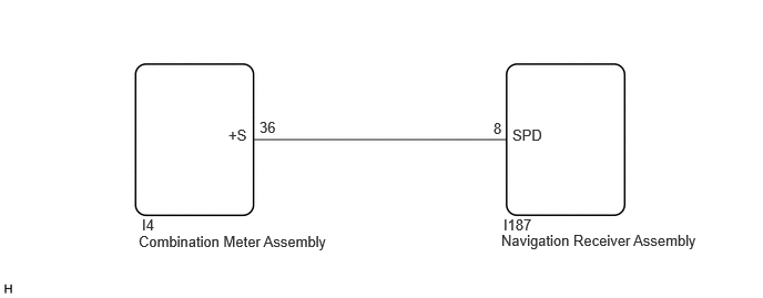
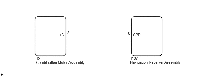
CAUTION / NOTICE / HINT
- NOTICE:
-
Depending on the parts that are replaced during vehicle inspection or maintenance, performing initialization, registration or calibration may be needed.
PROCEDURE
Check vehicle control history (RoB)
Using the GTS, check for vehicle control history (RoB).
- Body Electrical > Navigation System > Utility
-
Tester Display Vehicle Control History (RoB) - 50005 496 55
- Result:
Result Proceed to Vehicle control history (RoB) X8023 is output A Vehicle control history (RoB) is not output B
A
B
Check that optional components are not installed.
- Result:
Result Proceed to Optional components are installed A Optional components are not installed B
A
B
Remove optional components.
Turn the ignition switch off and back to ON.
- Result:
Proceed to NEXT
NEXT
- HINT:
-
For enter diagnostic mode and screen transition, refer toAudio / Visual / Telematics>NAVIGATION / MULTI INFO DISPLAY>NAVIGATION SYSTEM (w/o RST Switch (except 10.25 Inch Display))>DIAGNOSIS SYSTEM202205,999999,_56,_080752,_0528911,RM1000000022MWP,
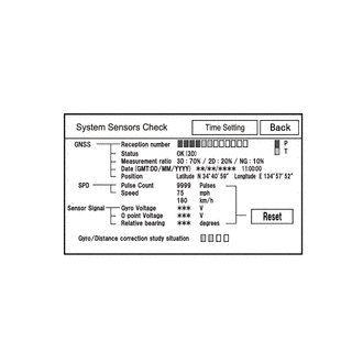
Enter diagnostic mode.
Enter diagnostic mode.
Select "Function Check/Setting" from the "Service Menu" screen.
Select "System Sensors Check" from the "Function Check/Setting I" screen.
System sensors check
Drive the vehicle and confirm that the displayed Speed changes in accordance with the vehicle driving condition.
- Result:
Result Proceed to Speed changes A Speed does not change (for Optitron Meter Type) B Speed does not change (for TFT Meter Type) C
A
B
C
Disconnect the I4 combination meter assembly connector.
Disconnect the I187 navigation receiver assembly connector.
Measure the resistance according to the value(s) in the table below.
- Standard Resistance:
Tester Connection Condition Specified Condition I4-36 (+S) - I187-8 (SPD) Always Below 1 Ω I4-36 (+S) or I187-8 (SPD) - Body ground Always 10 kΩ or higher
- Result:
Proceed to OK NG
OK
NG
Disconnect the I5 combination meter assembly connector.
Disconnect the I187 navigation receiver assembly connector.
Measure the resistance according to the value(s) in the table below.
- Standard Resistance:
Tester Connection Condition Specified Condition I5-8 (+S) - I187-8 (SPD) Always Below 1 Ω I5-8 (+S) or I187-8 (SPD) - Body ground Always 10 kΩ or higher
- Result:
Proceed to OK NG
OK
NG