NR Series EMISSION CONTROL MONOLITHIC CONVERTER INSTALLATION
PROCEDURE

 17279
1.INSTALL OUTLET TURBINE ELBOW GASKET
17279
1.INSTALL OUTLET TURBINE ELBOW GASKET
Install a new outlet turbine elbow gasket to the turbocharger sub-assembly.
25051
2.INSTALL EXHAUST MANIFOLD CONVERTER SUB-ASSEMBLY (TWC: Front Catalyst)
Temporarily install the exhaust manifold converter sub-assembly (TWC: Front Catalyst) to the turbocharger sub-assembly with 4 new nuts.
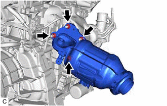
Tighten the 4 nuts in the order shown in the illustration.
- Torque:
- 40 N*m (408 kgf*cm, 30 ft.*lbf)
25586
3.INSTALL NO. 1 MANIFOLD CONVERTER INSULATOR
Temporarily install the No. 1 manifold converter insulator to the exhaust manifold converter sub-assembly (TWC: Front Catalyst) with the 3 bolts.
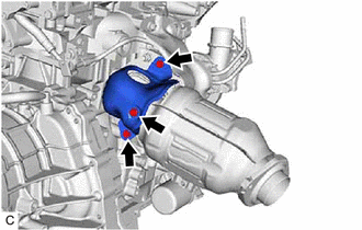
Tighten the 3 bolts in the order shown in the illustration.
- Torque:
- 10 N*m (102 kgf*cm, 7 ft.*lbf)
17272
4.INSTALL NO. 2 TURBO INSULATOR
Temporarily install the No. 2 turbo insulator to the cylinder head sub-assembly and heat insulator bracket with the 2 bolts.
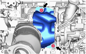
Tighten the 2 bolts in the order shown in the illustration.
- Torque:
- 10 N*m (102 kgf*cm, 7 ft.*lbf)
17163
5.INSTALL NO. 1 HEAT INSULATOR BRACKET
- HINT:
-
Perform this procedure when it is necessary to replace the No. 1 heat insulator bracket.
Type A:
Install the No. 1 heat insulator bracket to the cylinder block sub-assembly with the bolt.
- Torque:
- 43 N*m (438 kgf*cm, 32 ft.*lbf)
Type B:
Install the No. 1 heat insulator bracket to the cylinder block sub-assembly with the 2 bolts.
- Torque:
- 43 N*m (438 kgf*cm, 32 ft.*lbf)
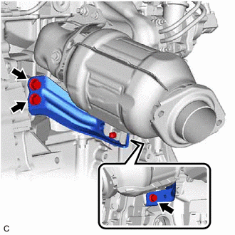
Temporarily install the manifold support bracket to the cylinder block sub-assembly and exhaust manifold converter sub-assembly (TWC: Front Catalyst) with the 3 bolts.
- NOTICE:
-
Tighten the 3 bolts until they contact the surface of the manifold support bracket.
Tighten the 3 bolts.
- Torque:
- 40 N*m (408 kgf*cm, 30 ft.*lbf)
| *a | Bolt Position |
| *b | Correct |
| *c | Incorrect |
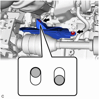
Temporarily install the driveshaft heat insulator sub-assembly to the No. 1 heat insulator bracket and manifold support bracket with the bolt and nut as shown in the illustration.
- NOTICE:
- ·
Tighten the nut and bolt until they contact the surface of the driveshaft heat insulator sub-assembly.
·Do not install the drive shaft heat insulator sub-assembly in the uppermost position. If the drive shaft heat insulator sub-assembly is installed in the uppermost position, damage may occur due to stress from distortion caused by high temperatures.
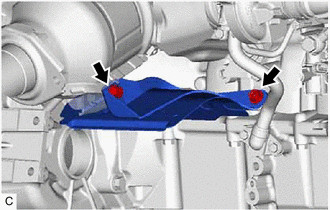
Tighten the bolt and nut in the order shown in the illustration.
- Torque:
- 17.6 N*m (179 kgf*cm, 13 ft.*lbf)
25591
6.INSTALL MANIFOLD SUPPORT BRACKET
Temporarily install the manifold support bracket to the cylinder block sub-assembly and exhaust manifold converter sub-assembly (TWC: Front Catalyst) with the 3 bolts.
- NOTICE:
-
Tighten the 3 bolts until they contact the surface of the manifold support bracket.
Tighten the 3 bolts.
- Torque:
- 40 N*m (408 kgf*cm, 30 ft.*lbf)
12321B
7.INSTALL DRIVE SHAFT HEAT INSULATOR SUB-ASSEMBLY
| *a | Bolt Position |
| *b | Correct |
| *c | Incorrect |
Temporarily install the driveshaft heat insulator sub-assembly to the No. 1 heat insulator bracket and manifold support bracket with the bolt and nut as shown in the illustration.
- NOTICE:
- ·
Tighten the nut and bolt until they contact the surface of the driveshaft heat insulator sub-assembly.
·Do not install the drive shaft heat insulator sub-assembly in the uppermost position. If the drive shaft heat insulator sub-assembly is installed in the uppermost position, damage may occur due to stress from distortion caused by high temperatures.
Tighten the bolt and nut in the order shown in the illustration.
- Torque:
- 17.6 N*m (179 kgf*cm, 13 ft.*lbf)
58151
8.INSTALL FRONT NO. 1 FLOOR HEAT INSULATOR
17410
9.INSTALL FRONT EXHAUST PIPE ASSEMBLY (TWC: Rear Catalyst)
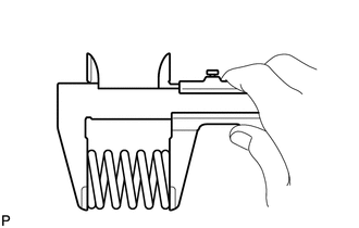
Using a vernier caliper, measure the free length of the compression springs.
| Minimum Free Length | Front Side | 41.5 mm (1.63 in.) |
| Rear Side | 38.5 mm (1.52 in.) |
If the free length is less than the minimum, replace the compression spring.
Temporarily install 2 new gaskets to the exhaust manifold converter sub-assembly (TWC: Front Catalyst) and front exhaust pipe assembly (TWC: Rear Catalyst).
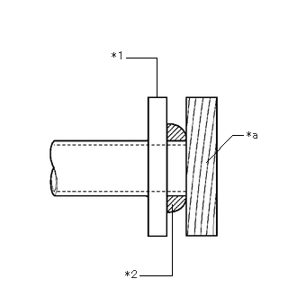
| *1 | Exhaust Manifold Converter Sub-assembly (TWC: Front Catalyst) or Front Exhaust Pipe Assembly (TWC: Rear Catalyst) |
| *2 | Gasket |
| *a | Wooden Block |
Using a plastic hammer and wooden block, tap in the gasket until its surface is flush with the exhaust manifold converter sub-assembly (TWC: Front Catalyst) and front exhaust pipe assembly (TWC: Rear Catalyst).
- NOTICE:
- ·
Be sure to install the gasket in the correct direction.
·Do not reuse the gasket.
·Do not damage the gasket.
·Do not push in the gasket by using the exhaust pipe when connecting it.
Connect the front exhaust pipe assembly (TWC: Rear Catalyst) to the 2 exhaust pipe supports.
Install the front exhaust pipe assembly (TWC: Rear Catalyst) to the exhaust manifold converter sub-assembly (TWC: Front Catalyst) with the 2 compression springs and 2 bolts.
- Torque:
- 43 N*m (438 kgf*cm, 32 ft.*lbf)
- HINT:
-
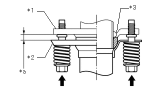 2.406,0.771 2.51,0.167 2.51,0.167 2.677,0.167 false 0.771,0.229 0.906,0.229 0.906,0.229 1.156,0.594 false 0.771,1.198 0.927,1.198 0.927,1.198 1.094,0.896 false 0.406,1.417 0.615,1.573 0.208,0.156 10 *a 0.573,0.146 0.823,0.302 0.25,0.156 10 *1 0.573,1.125 0.813,1.313 0.24,0.188 10 *2 2.698,0.083 2.927,0.26 0.229,0.177 10 *3
*1 Exhaust Manifold Converter Sub-assembly (TWC: Front Catalyst) *2 Front Exhaust Pipe Assembly (TWC: Rear Catalyst) *3 Gasket *a Space between Flanges: 8.5 mm (0.335 in.)
-
After installation, check that the space between the flanges of the exhaust manifold (TWC: Front Catalyst) and front exhaust pipe assembly (TWC: Rear Catalyst) is consistent front-to-rear and left-to-right.
Install the front exhaust pipe assembly (TWC: Rear Catalyst) to the tail exhaust pipe assembly with the 2 compression springs and 2 bolts.
- Torque:
- 43 N*m (438 kgf*cm, 32 ft.*lbf)
- HINT:
-
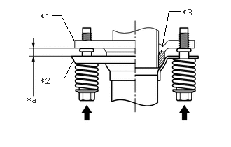 2.396,0.771 2.51,0.167 2.51,0.167 2.677,0.167 false 0.771,0.229 0.906,0.229 0.906,0.229 1.104,0.604 false 0.781,1.188 0.938,1.188 0.938,1.188 1.094,0.885 false 0.406,1.417 0.573,1.573 0.167,0.156 10 *a 0.604,0.177 0.802,0.375 0.198,0.198 10 *1 0.604,1.135 0.813,1.333 0.208,0.198 10 *2 2.719,0.115 2.885,0.271 0.167,0.156 10 *3
*1 Front Exhaust Pipe Assembly (TWC: Rear Catalyst) *2 Tail Exhaust Pipe Assembly *3 Gasket *a Space between Flanges: 6.5 mm (0.256 in.)
-
After installation, check that the space between the flanges of the front exhaust pipe assembly (TWC: Rear Catalyst) and tail exhaust pipe assembly is consistent front-to-rear and left-to-right.
Engage the wire harness clamp.
Connect the air fuel ratio sensor connector.
57533B
10.INSTALL FRONT FLOOR CENTER BRACE
58166A
11.INSTALL FRONT FLOOR COVER LH
58165C
12.INSTALL FRONT FLOOR COVER RH
- HINT:
-
Perform the same procedure as for the front floor cover LH.
12611
13.INSTALL NO. 1 ENGINE COVER
Install the No. 1 engine cover to the cylinder head cover sub-assembly and cylinder head sub-assembly.
89467B
14.INSTALL AIR FUEL RATIO SENSOR
17301C
15.INSTALL INLET NO. 1 AIR DUCT SUB-ASSEMBLY
Connect the inlet No. 1 air duct sub-assembly to the turbocharger sub-assembly.
Tighten the hose clamp.
- Torque:
- 4.0 N*m (41 kgf*cm, 35 in.*lbf)
Connect the No. 3 vacuum transmitting hose assembly to the turbocharger sub-assembly.
Connect the intake air control valve (air by-pass valve assembly) connector.
Connect the inlet No. 1 air duct sub-assembly to the fuel pump protector with the bolt.
- Torque:
- 10 N*m (102 kgf*cm, 7 ft.*lbf)
Engage the 3 clamps and install the No. 1 vacuum transmitting hose assembly to the inlet No. 1 air duct sub-assembly.
Connect the No. 1 vacuum transmitting hose assembly to the vacuum pump assembly.
Install the vacuum tank to the inlet No. 1 air duct sub-assembly with the 2 bolts.
- Torque:
- 9.0 N*m (92 kgf*cm, 80 in.*lbf)
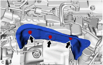
Temporarily install the No. 1 turbo insulator to the vacuum tank with the 3 bolts.
Tighten the 3 bolts in the order shown in the illustration.
- Torque:
- 10 N*m (102 kgf*cm, 7 ft.*lbf)
Apply a light coat of engine oil to the O-ring of the No. 4 ventilation hose.
Install the No. 4 ventilation hose to the inlet No. 1 air duct sub-assembly with the bolt.
- Torque:
- 10 N*m (102 kgf*cm, 7 ft.*lbf)
Apply a light coat of engine oil to the O-ring of the ventilation hose.
Install the ventilation hose to the inlet No. 1 air duct sub-assembly with the bolt.
- Torque:
- 10 N*m (102 kgf*cm, 7 ft.*lbf)
Engage the 2 clamps and connect the No. 1 vacuum transmitting hose assembly.
Connect the No. 1 vacuum transmitting hose assembly to the vacuum tank.
25861A
16.INSTALL NO. 2 VACUUM SWITCHING VALVE BRACKET
Install the No. 2 vacuum switching valve bracket to the cylinder head sub-assembly with the 3 bolts.
- Torque:
- 10 N*m (102 kgf*cm, 7 ft.*lbf)
25819
17.INSTALL VACUUM REGULATING VALVE ASSEMBLY
17360A
18.INSTALL AIR TUBE ASSEMBLY
Connect the air tube assembly to the turbocharger sub-assembly.
Tighten the hose clamp.
- Torque:
- 6.3 N*m (64 kgf*cm, 56 in.*lbf)
Connect the No. 2 intercooler water hose and No. 3 intercooler water hose to the No. 1 water hose clamp bracket.
Connect the No. 2 intercooler water hose and No. 3 intercooler water hose to the turbocharger sub-assembly and slide the 2 clips to secure them.
Install the air tube assembly to the cylinder head cover sub-assembly with the bolt.
- Torque:
- 10 N*m (102 kgf*cm, 7 ft.*lbf)
82121
19.INSTALL ENGINE WIRE
Install the wire harness clamp bracket to the cylinder head sub-assembly with the 2 bolts.
- Torque:
- 8.0 N*m (82 kgf*cm, 71 in.*lbf)


|
Bolt |

|
Nut |

|
Connector |
Engage the 3 wire harness clamps.
Install the bolt and nut.
- Torque:
- 8.0 N*m (82 kgf*cm, 71 in.*lbf)
Connect the 7 connectors.
17705
20.INSTALL AIR CLEANER CAP WITH AIR CLEANER HOSE
17751
21.INSTALL INLET NO. 1 AIR CLEANER
53289A
22.INSTALL RADIATOR SUPPORT OPENING COVER
55225C
23.INSTALL DASH PANEL HEAT INSULATOR
55701J
24.INSTALL OUTER COWL TOP PANEL SUB-ASSEMBLY
55737B
25.INSTALL NO. 1 HEATER AIR DUCT SPLASH SHIELD SEAL
26.INSTALL WINDSHIELD WIPER MOTOR AND LINK ASSEMBLY
27.INSTALL INTERCOOLER ASSEMBLY
28.INSPECT FOR EXHAUST GAS LEAK