NR Series INTAKE / EXHAUST INTERCOOLER INSTALLATION
PROCEDURE

 17940D
1.INSTALL INTERCOOLER ASSEMBLY
17940D
1.INSTALL INTERCOOLER ASSEMBLY
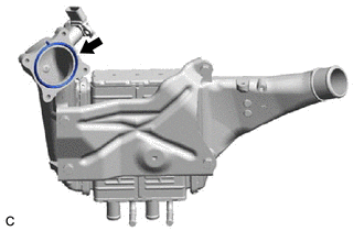
| *a | Protrusion |
Install a new throttle body gasket to the intercooler assembly with the protrusion of the throttle body gasket oriented as shown in the illustration.
Temporarily install the intercooler assembly to the air tube assembly with the hose clamp.
Temporarily install the intercooler assembly to the throttle body with motor assembly with the 2 bolts and 2 nuts.
Connect the No. 2 turbo water pipe sub-assembly to the intercooler assembly with the 2 bolts.
- Torque:
- 10 N*m (102 kgf*cm, 7 ft.*lbf)
Connect the 2 No. 1 turbo water hoses to the intercooler assembly and slide the 2 clips to secure them.
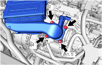
Tighten the 2 bolts and 2 nuts in the order shown in the illustration.
- Torque:
- 10 N*m (102 kgf*cm, 7 ft.*lbf)
Tighten the hose clamp.
- Torque:
- 6.3 N*m (64 kgf*cm, 56 in.*lbf)
16554C
2.CONNECT NO. 4 INTERCOOLER COOLING WATER HOSE
Connect the No. 4 intercooler cooling water hose to the intercooler assembly and slide the clip to secure it.
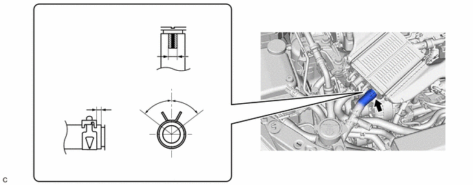
| *a | Up | *b | Front |
| *c | 60° | *d | 1 to 5 mm (0.0394 to 0.197 in.) |
| *e | Paint Mark | *f | Matchmark |
| *g | Paint Mark Area | - | - |
- HINT:
- ·
Position the No. 4 intercooler cooling water hose and clip as shown in the illustration.
·Push in the No. 4 intercooler cooling water hose until it contacts the stopper.
16551C
3.CONNECT NO. 1 INTERCOOLER COOLING WATER HOSE
Connect the No. 1 intercooler cooling water hose to the intercooler assembly and slide the clip to secure it.
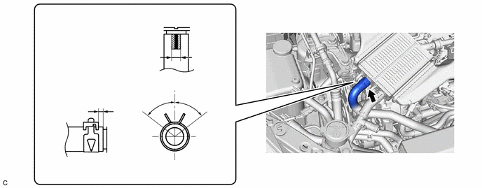
| *a | Up | *b | Front |
| *c | 60° | *d | 1 to 5 mm (0.0394 to 0.197 in.) |
| *e | Paint Mark | *f | Matchmark |
| *g | Paint Mark Area | - | - |
- HINT:
- ·
Position the No. 1 intercooler cooling water hose and clip as shown in the illustration.
·Push in the No. 1 intercooler cooling water hose until it contacts the stopper.
89421K
4.INSTALL NO. 1 TURBO PRESSURE SENSOR
5.ADD COOLANT (for Intercooler)
6.INSPECT FOR COOLANT LEAK (for Intercooler)