K313 CVT CONTINUOUSLY VARIABLE TRANSAXLE SYSTEM P07407F Torque Converter Clutch Actuator Stuck Off P099A7F Shift Solenoid "G" Control Actuator Stuck Off P27567F Torque Converter Clutch Pressure Control Solenoid Control Actuator Stuck Off
DESCRIPTION
The ECM uses the shift solenoid valves SC and SL to switch control of the shift solenoid valve SLU between forward and reverse clutch control and lock-up control in response to driving conditions.
- HINT:
-
If DTC P07407F is stored after the engine has stalled, the lock-up shift solenoid valve (shift solenoid valve SL) may be malfunctioning.
| DTC No. | Detection Item | DTC Detection Condition | Trouble Area | MIL | Memory | Note |
|---|---|---|---|---|---|---|
| P07407F | Torque Converter Clutch Actuator Stuck Off | Any of the following conditions are met (2-trip detection logic):
·
When the ECM sends a lock-up OFF command and turns the shift solenoid valves SC and SL OFF, the difference between the engine speed (NE) and input turbine speed (NT) is 25 rpm or less for 1 second or more. ·
When the ECM turns the shift solenoid valves SC and SL ON, the difference between the input turbine speed (NT) and primary pulley speed (NIN) is 300 rpm or more for 1 second or more. ·
While the vehicle is driven, a lock-up ON command is sent, but lock-up control is not performed for 1 second or more. |
·
Transmission valve body assembly (Shift solenoid valve SL) ·
Torque converter assembly ·
Continuously variable transaxle assembly |
Comes on | DTC stored | SAE Code:
P0741 |
| P099A7F | Shift Solenoid "G" Control Actuator Stuck Off | Any of the following conditions are met (2-trip detection logic):
·
When the ECM sends a lock-up ON command and turns the shift solenoid valves SC and SL ON, the difference between the engine speed (NE) and input turbine speed (NT) is 25 rpm or less for 1 second or more. ·
When the ECM turns the shift solenoid valves SC and SL OFF, the difference between the input turbine speed (NT) and primary pulley speed (NIN) is 300 rpm or more for 1 second or more. ·
While the vehicle is driven, a lock-up ON command is sent, but lock-up control is not performed for 1 second or more. |
·
Transmission valve body assembly (Shift solenoid valve SC) ·
Torque converter assembly ·
Continuously variable transaxle assembly |
Comes on | DTC stored | SAE Code:
P075B |
| P27567F | Torque Converter Clutch Pressure Control Solenoid Control Actuator Stuck Off | Either of the following conditions is met (2-trip detection logic):
·
When the ECM sends a lock-up ON command and turns the shift solenoid valves SC and SLU OFF and SL ON, the difference between the engine speed (NE) and input turbine speed (NT) is 25 rpm or less for 1 second or more. ·
While the vehicle is driven, a lock-up signal is turned ON, but the lock-up remains OFF for 1 second or more. |
·
Transmission valve body assembly (Shift solenoid valve SLU) ·
Torque converter assembly ·
Continuously variable transaxle assembly |
Comes on | DTC stored | SAE Code:
P2757 |
| Vehicle Condition | ||||
|---|---|---|---|---|
| Pattern 1 | Pattern 2 | Pattern 3 | ||
| Diagnostic Condition | The ECM sends a lock-up OFF command and turns the shift solenoid valves SC and SL OFF. | ○ | - | - |
| The ECM turns the shift solenoid valves SC and SL ON. | - | ○ | - | |
| The vehicle is driven and a lock-up ON command is sent. | - | - | ○ | |
| Malfunction Condition | The difference between the engine speed (NE) and input turbine speed (NT) is 25 rpm or less. | ○ | - | - |
| The difference between the input turbine speed (NT) and primary pulley speed (NIN) is 300 rpm or more. | - | ○ | - | |
| Lock-up control is not performed. | - | - | ○ | |
| Duration | 1 second or more | 1 second or more | 1 second or more | |
| Detection Logic | 2-trip detection logic | 2-trip detection logic | 2-trip detection logic | |
| Vehicle Condition | ||||
|---|---|---|---|---|
| Pattern 1 | Pattern 2 | Pattern 3 | ||
| Diagnostic Condition | The ECM turns the shift solenoid valves SC and SL OFF. | ○ | - | - |
| The vehicle is being driven. | - | ○ | - | |
| The ECM sends a lock-up ON command and turns the shift solenoid valves SC and SL ON. | - | - | ○ | |
| Malfunction Condition | The difference between the input turbine speed (NT) and primary pulley speed (NIN) is 300 rpm or more. | ○ | - | - |
| The lock-up ON command is sent, but lock-up control is not performed. | - | ○ | - | |
| The difference between the engine speed (NE) and input turbine speed (NT) is 25 rpm or less. | - | - | ○ | |
| Duration | 1 second or more | 1 second or more | 1 second or more | |
| Detection Logic | 2-trip detection logic | 2-trip detection logic | 2-trip detection logic | |
| Vehicle Condition | |||
|---|---|---|---|
| Pattern 1 | Pattern 2 | ||
| Diagnostic Condition | The ECM sends a lock-up ON command, and turns the shift solenoid valves SC and SLU OFF and SL ON. | ○ | - |
| The vehicle is being driven. | - | ○ | |
| Malfunction Condition | The difference between the engine speed (NE) and input turbine speed (NT) is 25 rpm or less. | ○ | - |
| The lock-up signal is turned ON, but the lock-up remains OFF. | - | ○ | |
| Duration | 1 second or more | 1 second or more | |
| Detection Logic | 2-trip detection logic | 2-trip detection logic | |
- HINT:
-
These DTCs are output when either of the above detection patterns is met.
MONITOR DESCRIPTION
When performing lock-up control (on/off) of the torque converter, the ECM compares the transmission revolution sensor (NT) output speed and engine speed (NE) to detect mechanical malfunctions in the shift solenoid valves SL and SC.
If the torque converter does not lock-up while a lock-up ON command is being sent, the ECM detects it as a mechanical malfunction of the shift solenoid valve SLU.
If the difference between the engine speed (NE) and transmission revolution sensor (NT) output speed or transmission revolution sensor (NIN) output speed and transmission revolution sensor (NT) output speed is outside of the threshold, the ECM detects the malfunction, illuminates the MIL and stores a DTC.
CONFIRMATION DRIVING PATTERN
- CAUTION:
-
When performing the confirmation driving pattern, obey all speed limits and traffic laws.
- HINT:
- ·
After repairs have been completed, clear the DTCs and then check that the vehicle has returned to normal by performing the following All Readiness check procedure.
·When clearing the permanent DTCs, refer to the Clear Permanent DTC procedure.
Connect the GTS to the DLC3.
Turn the ignition switch to ON and turn the GTS on.
Clear the DTCs (even if no DTCs are stored, perform the clear DTC procedure).
Turn the ignition switch off and wait for 2 minutes or more.
Turn the ignition switch to ON and turn the GTS on.
Start the engine.
Drive the vehicle and confirm the lock-up on and off conditions according to Road Test. [*1]
- HINT:
-
[*1]: Normal judgment procedure.
-
The normal judgment procedure is used to complete DTC judgment and also used when clearing permanent DTCs.
Stop the vehicle.
Enter the following menus: Powertrain / Transmission / Utility / All Readiness.
Input the DTC: P07407F, P099A7F or P27567F.
Check the DTC judgment result.
| GTS Display | Description |
|---|---|
| NORMAL | ·
DTC judgment completed ·
System normal |
| ABNORMAL | ·
DTC judgment completed ·
System abnormal |
| INCOMPLETE | ·
DTC judgment not completed ·
Perform driving pattern after confirming DTC enabling conditions |
| N/A | ·
Unable to perform DTC judgment ·
Number of DTCs which do not fulfill DTC preconditions has reached ECU memory limit |
- HINT:
- ·
If the judgment result shows NORMAL, the system is normal.
·If the judgment result shows ABNORMAL, the system has a malfunction.
·If the judgment result shows INCOMPLETE or N/A, perform the normal judgment procedure again.
WIRING DIAGRAM
Refer to DTC P074011, P099A11 and P275613.
for P074011: Click hereDrivetrain>K313 (CVT)>CONTINUOUSLY VARIABLE TRANSAXLE SYSTEM>P074011201906,999999,_52,_080728,_0392261,RM100000001HP9M,P074011
for P099A11: Click hereDrivetrain>K313 (CVT)>CONTINUOUSLY VARIABLE TRANSAXLE SYSTEM>P099A11201906,999999,_52,_080728,_0392261,RM100000001HP9Q,P099A11
for P275613: Click hereDrivetrain>K313 (CVT)>CONTINUOUSLY VARIABLE TRANSAXLE SYSTEM>P275613201906,999999,_52,_080728,_0392261,RM100000001HP9T,P275613
CAUTION / NOTICE / HINT
- CAUTION:
- ·
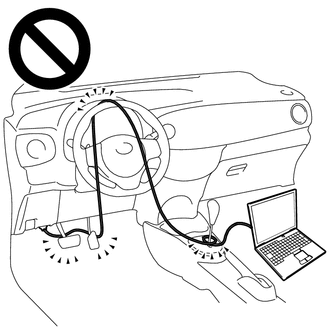
Strictly observe posted speed limits, traffic laws and road conditions.
·Do not drive the vehicle with the cable of the GTS contacting the pedals, shift lever or steering wheel.
·Driving the vehicle with the cable of the GTS contacting these areas could impede vehicle control, resulting in a serious accident.
- ·
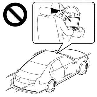
Do not operate the GTS while driving the vehicle.
·Operating the GTS while driving the vehicle will prevent you from paying sufficient attention to vehicle surroundings, and could result in a serious accident.
- NOTICE:
- ·
Perform the universal trip to clear permanent DTCs.
·Perform initialization when parts related to the continuously variable transaxle system are replaced.
·Check that no DTCs are stored after performing initialization.
PROCEDURE
Connect the GTS to the DLC3.
Turn the ignition switch to ON.
Turn the GTS on.
Enter the following menus: Powertrain / Transmission / Trouble Codes.
- Powertrain > Transmission > Trouble Codes
- 50001 373
Read the DTCs using the GTS.
- HINT:
-
If any DTCs other than P07407F, P099A7F or P27567F are output, perform troubleshooting for those DTCs first.
- Result:
Result Proceed to Only DTC P07407F, P099A7F and/or P27567F is output A DTC P07407F, P099A7F and/or P27567F and other DTCs are output B
A
B
Clear the DTCs.
- Powertrain > Transmission > Clear DTCs
- 50002 373
- Result:
Proceed to NEXT
NEXT
- CAUTION:
-
Strictly observe posted speed limits, traffic laws and road conditions when performing a drive test.
- NOTICE:
- ·
This test must be performed after checking and confirming that the engine is normal.
·Perform this test with the CVT fluid temperature between 50 and 100°C (122 and 212°F).
·Perform this test with the air conditioning off.
- HINT:
- ·
Lock-up control will not operate when the CVT fluid temperature is 40°C (104°F) or less and the vehicle speed is 60 km/h (37 mph) or less, or when the CVT fluid temperature is 5°C (41°F) or less.
·Lock-up control will not operate when the engine coolant temperature is 30°C (86°F) or less.
·The lock-up OFF vehicle speed may vary depending on the electrical load, and air conditioning and brake operations.
Connect the GTS to the DLC3.
Start the engine.
Turn the GTS on.
Enter the following menus: Powertrain / Transmission / Data List / Engine Speed, NT Sensor Speed, NIN Sensor Speed, Lock Up Status, Solenoid (SL) and Solenoid (SC).
According to the display on the GTS, read the Data List while driving.
- Powertrain > Transmission > Data List
-
Tester Display Measurement Item Range Normal Condition Diagnostic Note Engine Speed Engine speed Min.: 0 rpm
Max.: 16383 rpm680 to 780 rpm: Engine idling (shift lever in N, engine warmed up and A/C switch off) When the crankshaft position sensor is malfunctioning, "Engine Speed" is approximately 0 rpm or varies greatly from the actual engine speed. NT Sensor Speed Input turbine speed (NT) Min.: 0 rpm
Max.: 12750 rpm·Equal to engine speed (NE): Lock-up ON (After warming up engine)
·Nearly equal to engine speed (NE): Lock-up OFF (Engine idling with shift lever in P or N)
·0 rpm: Vehicle stopped with shift lever in R
Data is displayed in increments of 50 rpm. NIN Sensor Speed Primary pulley speed (NIN) Min.: 0 rpm
Max.: 12750 rpm·0 rpm: Vehicle stopped
·Equal to engine speed (NE): Lock-up ON (After warming up engine)
Data is displayed in increments of 50 rpm. Lock Up Status Lock-up OFF or ON ·ON: Lock-up operating
·OFF: Lock-up not operating
- Solenoid (SL) Shift solenoid valve SL status OFF or ON ·ON: Lock-up permitted
·OFF: Lock-up not permitted
- Solenoid (SC) Shift solenoid valve SC status OFF or ON ·ON: For 1 second after moving shift lever from P to D or R, or N to D or R
·ON: Lock-up ON to OFF
·OFF: Engine idling
-
- Powertrain > Transmission > Data List
-
Tester Display Engine Speed NT Sensor Speed NIN Sensor Speed Lock Up Status Solenoid (SL) Solenoid (SC) - 50003 373 211,174,364,178,407,406
- Result:
Result Proceed to When Lock Up Status is ON, the value of NT Sensor Speed is lower than the value of Engine Speed. A When Solenoid (SL) and Solenoid (SC) are OFF, the value of NT Sensor Speed is equal to the value of Engine Speed. When Solenoid (SL) and Solenoid (SC) are ON, the difference between the value of NT Sensor Speed and NIN Sensor Speed is large. When Lock Up Status is ON, the value of NT Sensor Speed is equal to the value of Engine Speed. B When Solenoid (SL) and Solenoid (SC) are OFF, the value of NT Sensor Speed is lower than the value of Engine Speed. When Solenoid (SL) and Solenoid (SC) are ON, the NT Sensor Speed is equal to the value of NIN Sensor Speed.
A
B
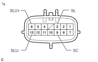
| *a | Component without harness connected
(Transmission Wire) |
Remove the oil strainer assembly.
Click hereDrivetrain>K313 (CVT)>VALVE BODY ASSEMBLY>REMOVAL201906,999999,_52,_080728,_0392279,RM100000001HPC1,
Disconnect the C60 transmission wire connector.
Apply battery voltage to the transmission wire and check that each valve moves and makes an operating noise.
- OK:
Measurement Condition Specified Condition ·Battery positive (+) → 3 (SL)
·Battery negative (-) → Transmission valve body assembly
Valve moves and makes an operating noise ·Battery positive (+) → 9 (SC)
·Battery negative (-) → Transmission valve body assembly
Valve moves and makes an operating noise ·Battery positive (+) → 6 (SLU+)
·Battery negative (-) → 13 (SLU-)
Valve moves and makes an operating noise
Check the transmission valve body assembly.
Click hereDrivetrain>K313 (CVT)>VALVE BODY ASSEMBLY>REMOVAL201906,999999,_52,_080728,_0392279,RM100000001HPC1,
- OK:
There is no foreign matter on each valve and they operate smoothly.
- Result:
Proceed to OK NG
OK
NG
Replace the continuously variable transaxle assembly.
When Not Using the Engine Support Bridge: Click hereDrivetrain>K313 (CVT)>CONTINUOUSLY VARIABLE TRANSAXLE ASSEMBLY (When Not Using the Engine Support Bridge)>COMPONENTS201906,999999,_52,_080728,_0392264,RM100000001HPAH,
When Using the Engine Support Bridge: Click hereDrivetrain>K313 (CVT)>CONTINUOUSLY VARIABLE TRANSAXLE ASSEMBLY (When Using the Engine Support Bridge)>COMPONENTS201906,202107,_52,_080728,_0392263,RM100000001HPAG,202107,202307,_52,_080728,_0392263,RM100000001YHL2,202307,999999,_52,_080728,_0392263,RM100000002DACK,
- Result:
Proceed to NEXT
NEXT
Replace the torque converter assembly.
When Not Using the Engine Support Bridge: Click hereDrivetrain>K313 (CVT)>CONTINUOUSLY VARIABLE TRANSAXLE ASSEMBLY (When Not Using the Engine Support Bridge)>COMPONENTS201906,999999,_52,_080728,_0392264,RM100000001HPAH,
When Using the Engine Support Bridge: Click hereDrivetrain>K313 (CVT)>CONTINUOUSLY VARIABLE TRANSAXLE ASSEMBLY (When Using the Engine Support Bridge)>COMPONENTS201906,202107,_52,_080728,_0392263,RM100000001HPAG,202107,202307,_52,_080728,_0392263,RM100000001YHL2,202307,999999,_52,_080728,_0392263,RM100000002DACK,
- Result:
Proceed to NEXT
NEXT
Replace the transmission valve body assembly.
- Result:
Proceed to NEXT
NEXT