NR Series ENGINE MECHANICAL ENGINE UNIT INSTALLATION
PROCEDURE

 1.INSTALL WIRE HARNESS CLAMP BRACKET
Install the wire harness clamp bracket to the timing chain cover assembly with the 2 bolts.
- Torque:
- 8.0 N*m (82 kgf*cm, 71 in.*lbf)
Install the wire harness clamp bracket to the stiffening crankcase assembly with the bolt.
- Torque:
- 10 N*m (102 kgf*cm, 7 ft.*lbf)
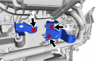
Install the 2 wire harness clamp brackets to the stiffening crankcase assembly with the 3 bolts.
- Torque:
- Bolt (A) : 10 N*m (102 kgf*cm, 7 ft.*lbf)
- Bolt (B) : 8.0 N*m (82 kgf*cm, 71 in.*lbf)
Install the wire harness clamp bracket to the cylinder head sub-assembly with the bolt.
- Torque:
- 8.0 N*m (82 kgf*cm, 71 in.*lbf)
Install the 2 wire harness clamp brackets to the cylinder head cover sub-assembly with the 3 bolts.
- Torque:
- 8.0 N*m (82 kgf*cm, 71 in.*lbf)
2.INSTALL STUD BOLT
Using an E8 "TORX" socket wrench, install the stud bolt to the timing chain cover assembly.
- Torque:
- 10 N*m (102 kgf*cm, 7 ft.*lbf)
17163
3.INSTALL NO. 1 HEAT INSULATOR BRACKET
Type A:
Install the No. 1 heat insulator bracket to the cylinder block sub-assembly with the bolt.
- Torque:
- 43 N*m (438 kgf*cm, 32 ft.*lbf)
Type B:
Install the No. 1 heat insulator bracket to the cylinder block sub-assembly with the 2 bolts.
- Torque:
- 43 N*m (438 kgf*cm, 32 ft.*lbf)
16261G
4.INSTALL NO. 1 WATER BY-PASS HOSE
Install the No. 1 water by-pass hose to the water inlet and slide the clip to secure it.
29300
5.INSTALL VACUUM PUMP ASSEMBLY
16206
6.INSTALL WATER BY-PASS PIPE SUB-ASSEMBLY

| *1 | Water By-pass Pipe Union Bolt |
Install a new water inlet pipe gasket and temporarily install the water by-pass pipe sub-assembly to the cylinder head sub-assembly with the water by-pass pipe union bolt and 3 bolts (A).
Tighten the water by-pass pipe union bolt and 3 bolts in the order shown in the illustration.
- Torque:
- Water By-pass Pipe Union Bolt : 36 N*m (367 kgf*cm, 27 ft.*lbf)
- Bolt (A) : 10 N*m (102 kgf*cm, 7 ft.*lbf)
23818
7.INSTALL FUEL VAPOR FEED PIPE
Install the fuel vapor feed pipe to the cylinder head cover sub-assembly with the 2 bolts.
- Torque:
- 10 N*m (102 kgf*cm, 7 ft.*lbf)
19500D
8.INSTALL NO. 1 IGNITION COIL
23100X
9.INSTALL FUEL (ENGINE ROOM SIDE) PUMP ASSEMBLY
23250
10.INSTALL FUEL INJECTOR ASSEMBLY
17201
11.INSTALL TURBOCHARGER SUB-ASSEMBLY