NR Series INTAKE / EXHAUST TURBOCHARGER INSTALLATION
CAUTION / NOTICE / HINT
- NOTICE:
-
Before installing the turbocharger sub-assembly, be sure to read Maintenance Precaution.
PROCEDURE

 1.INSTALL STUD BOLT
- HINT:
-
If a stud bolt is deformed or the threads are damaged, replace it.
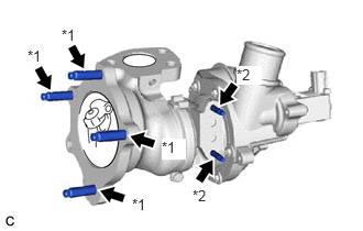
| *1 | Stud Bolt (A) |
| *2 | Stud Bolt (B) |
Using an E10 "TORX" socket wrench, install the 4 stud bolts (A) to the turbocharger sub-assembly.
- Torque:
- 19.5 N*m (199 kgf*cm, 14 ft.*lbf)
Using an E6 "TORX" socket wrench, install the 2 stud bolts (B) to the turbocharger sub-assembly.
- Torque:
- 5.0 N*m (51 kgf*cm, 44 in.*lbf)
17201
2.INSTALL TURBOCHARGER SUB-ASSEMBLY
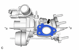
| *a | Claw |
Install a new turbocharger gasket to the turbocharger sub-assembly.
- HINT:
-
Make sure that the claws of the turbocharger gasket are facing the turbocharger sub-assembly.
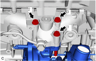
Temporarily install the turbocharger sub-assembly to the cylinder head sub-assembly with the 3 bolts in the order shown in the illustration.
- HINT:
-
Tighten the bolt by hand until it contacts the surface of the cylinder head sub-assembly.
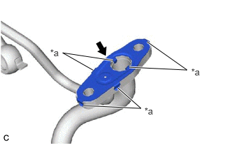
| *a | Claw |
Install a new inlet turbo oil gasket to the inlet turbo oil pipe sub-assembly.
- NOTICE:
-
Make sure that the inlet turbo oil gasket is installed in the correct direction.
- HINT:
-
Make sure that the claws of the inlet turbo oil gasket are facing the inlet turbo oil pipe sub-assembly.
| *a | Claw |
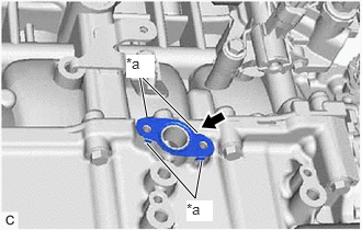
Install a new outlet No. 1 turbo oil gasket to the stiffening crankcase assembly.
- HINT:
-
Make sure that the claws of the outlet No. 1 turbo oil gasket are facing the stiffening crankcase assembly.
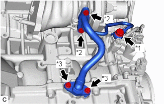
| *1 | Union Bolt |
| *2 | Bolt (A) |
| *3 | Bolt (B) |
Install a new gasket to the inlet turbo oil pipe sub-assembly.
Temporarily install the inlet turbo oil pipe sub-assembly to the turbocharger sub-assembly and cylinder block sub-assembly with the 2 bolts (A) and union bolt.
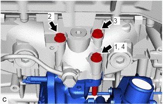
Tighten the 3 bolts in the order shown in the illustration.
- Torque:
- 35 N*m (357 kgf*cm, 26 ft.*lbf)
Tighten the 2 bolts (A).
- Torque:
- 12 N*m (122 kgf*cm, 9 ft.*lbf)
Temporarily tighten the union bolt.
Temporarily install the 2 bolts (B).
Tighten the union bolt.
- Torque:
- 36 N*m (367 kgf*cm, 27 ft.*lbf)
- NOTICE:
-
If the link that connects the gaskets is broken, remove the link by using side cutters or a similar tool.
Tighten the 2 bolts (B).
- Torque:
- 12 N*m (122 kgf*cm, 9 ft.*lbf)
Connect the intake air control valve (air by-pass valve assembly) connector.
16027
3.CONNECT NO. 1 TURBO WATER PIPE SUB-ASSEMBLY
Set a new water by-pass gasket.
Temporarily install the No. 1 turbo water pipe sub-assembly with the 2 nuts.
Temporarily install the bolt.

Tighten the 2 nuts and bolt in the order shown in the illustration.
- Torque:
- 12 N*m (122 kgf*cm, 9 ft.*lbf)
25051
4.INSTALL EXHAUST MANIFOLD CONVERTER SUB-ASSEMBLY
5.ADD ENGINE OIL
6.INSPECT FOR ENGINE OIL LEAK