NR Series FUEL FUEL INJECTOR INSTALLATION
PROCEDURE

 23255A
1.INSTALL FUEL INJECTOR SEAL
23255A
1.INSTALL FUEL INJECTOR SEAL
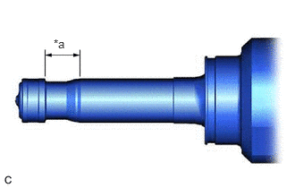
| *a | Area to be Cleaned |
Apply engine conditioner to the area shown in the illustration. Using a piece of cloth, clean carbon deposits from the fuel injector assembly and its grooves.
- NOTICE:
- ·
Do not clean the tip of the fuel injector assembly.
·Do not use a wire brush to clean the fuel injector assembly.
·If a fuel injector assembly is dropped or the tip of the fuel injector assembly is struck, replace it with a new one.
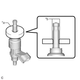
| *a | SST (Guide) |
| *b | Chamfer |
Apply engine oil to the fuel injector assembly contact surface of SST (guide), then attach SST (guide) to the fuel injector assembly with the chamfer facing the tip of the fuel injector assembly as shown in the illustration.
- SST
- 09260-39021 (09261-03020)
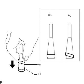
| *1 | Fuel Injector Seal |
| *a | SST (Holder) |
| *b | Correct |
| *c | Incorrect |
Install a new fuel injector seal to SST (holder).
- SST
- 09260-39021 (09261-03011)
- NOTICE:
-
Be careful not to install the fuel injector seal to SST (holder) at an angle. Doing so will stretch the fuel injector seal.
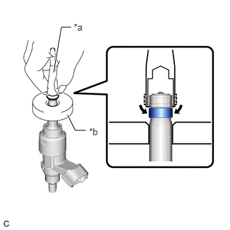
| *a | SST (Holder) |
| *b | SST (Guide) |
Install SST (holder) with the fuel injector seal to the tip of the fuel injector assembly. Slide the fuel injector seal downward into the fuel injector assembly groove with your fingers as shown in the illustration.
- SST
- 09260-39021 (09261-03011, 09261-03020)
- HINT:
-
Check that the fuel injector seal is seated in the fuel injector assembly groove as shown in the illustration.
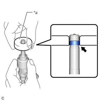
| *a | SST (Guide) |
Slowly slide SST (guide) toward the tip of the fuel injector assembly. When the fuel injector assembly contact surface of SST (guide) aligns with the fuel injector seal as shown in the illustration, hold the position for 5 seconds or more to fully seat the fuel injector seal into the fuel injector assembly groove.
- SST
- 09260-39021 (09261-03020)
- NOTICE:
-
Make sure the fuel injector seal is not pinched between SST (guide) and the edge of the fuel injector assembly groove. Replace the fuel injector seal if it becomes damaged.
- HINT:
- ·
Set SST (guide) so that its bottom surface is flush with the fuel injector seal.
·If it is difficult to slide SST (guide) upward, slowly wiggle it from side to side while sliding it up the fuel injector assembly little by little.
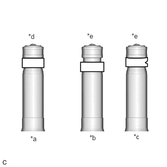
| *a | Normal |
| *b | Protruding |
| *c | Deformed |
| *d | Correct |
| *e | Incorrect |
After installing the fuel injector seals, check that they are not scratched, deformed or protruding from the fuel injector assembly groove.
- NOTICE:
-
If a fuel injector seal is scratched, deformed or protruding from the groove, replace it with a new one.
23250
2.INSTALL FUEL INJECTOR ASSEMBLY
- HINT:
-
Perform "Inspection After Repair" after replacing a fuel injector assembly.
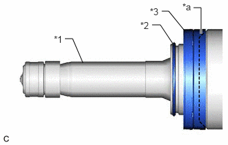
| *1 | Fuel Injector Assembly |
| *2 | C-ring |
| *3 | Injector Vibration Insulator |
| *a | Taper |
Install a new injector vibration insulator and C-ring to the fuel injector assembly.
- NOTICE:
- ·
Install the taper of the injector vibration insulator by aligning it with the taper of the fuel injector assembly.
·Check that the C-ring is securely seated in the groove of the fuel injector assembly.
Install a new O-ring and No. 1 fuel injector back-up ring to the fuel injector assembly as shown in the illustration.

| *1 | No. 1 Fuel Injector Back-up Ring | *2 | O-ring |
| *a | No. 1 Fuel Injector Back-up Ring Opening | *b | Overlapped |
| *c | Stretched | *d | Correct |
| *e | Incorrect | - | - |
- NOTICE:
- ·
Check that there is no foreign matter or damage on the O-ring groove of the fuel injector assembly.
·Make sure that the No. 1 fuel injector back-up ring is installed in the correct orientation.
·Make sure that the No. 1 fuel injector back-up ring and O-ring are installed in the correct order.
·Check that the opening of the No. 1 fuel injector back-up ring is not overlapped or stretched as shown in the illustration.
·After installing the O-ring, check that it is not contaminated with foreign matter and is not damaged.
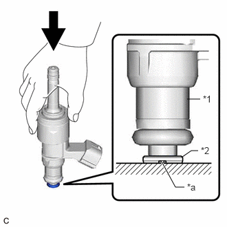
| *1 | Fuel Injector Assembly |
| *2 | No. 3 Fuel Injector Back-up Ring |
| *a | Notch |
With the notch of a new No. 3 fuel injector back-up ring facing downward, install the fuel injector assembly to the No. 3 fuel injector back-up ring as shown in the illustration.
- NOTICE:
- ·
Make sure that the No. 3 fuel injector back-up ring is installed in the correct orientation.
·After installing the No. 3 fuel injector back-up ring, make sure there is no damage or foreign matter.
Install the nozzle holder clamp to each fuel injector assembly.
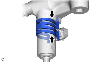
| *a | Protrusion |
| *b | Positioning Hole |

|
No Gap |
Align the protrusion of the nozzle holder clamp with the positioning hole of the fuel delivery pipe and insert the fuel injector assembly.
- NOTICE:
- ·
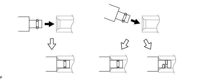
Make sure that there is no foreign matter or damage inside the fuel injector assembly installation holes (fuel delivery pipe).
·Do not allow gasoline to get on the O-rings or inside the installation holes.
·If it is difficult to insert the fuel injector assembly, apply new engine oil to the chamfer of the fuel injector assembly installation hole of the fuel delivery pipe. Be careful not to allow the fuel injector assembly to fall out of the fuel delivery pipe.
·Do not tilt the fuel injector assembly when inserting it into the fuel delivery pipe.
 0.115,0.104 3.083,2.667 2.969,2.563 3.25,0.104 6.667,2.667 3.417,2.563 2.25,1.083 2.417,1.5 2.417,1.5 2.583,1.5 true 5.417,1.083 5.583,1.5 5.583,1.5 5.75,1.5 true 1.313,1 1.313,1.417 false 4.333,0.771 4.333,1.104 false 0.24,0.167 0.552,0.365 0.313,0.198 10 false *a 3.354,0.167 3.667,0.365 0.313,0.198 10 false *b 1.24,1.448 1.552,1.646 0.313,0.198 10 false *1 4.281,1.125 4.594,1.323 0.313,0.198 10 false *1 2.635,1.427 2.948,1.625 0.313,0.198 10 false *2 5.802,1.427 6.115,1.625 0.313,0.198 10 false *2
*1 O-ring *2 Fuel Delivery Pipe *a Correct *b Incorrect
·Check that there is no gap between the fuel delivery pipe and the nozzle holder clamp.
· 1.073,1.656 1.51,1.656 true 1.74,1.646 2.271,1.24 2.271,1.24 2.469,1.24 true 2.521,1.167 2.833,1.323 0.313,0.156 10 false *a 0.906,1.583 1.219,1.74 0.313,0.156 10 false *b
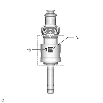
*a QR Code *b Flow Classification Number
As fuel injector assemblies with different flow classification numbers are incompatible, make sure the 4 fuel injector assemblies have the same flow classification number (the number to the left of the QR code (1, 2, 3, 4, 5, 6, 7, 8 or 9)).
- HINT:
-
When replacing the fuel injector assemblies for all cylinders, it is not necessary to use the same flow classification number as those currently installed to the vehicle. However, make sure to replace the fuel injector assemblies with new ones that all have the same flow classification number (1, 2, 3, 4, 5, 6, 7, 8 or 9).
23814B
3.INSTALL FUEL DELIVERY PIPE
Apply lubricant to the fuel injector assembly installation holes of the cylinder head sub-assembly.
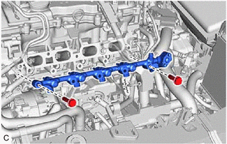
Temporarily install the fuel delivery pipe to the cylinder head sub-assembly with the 2 bolts.
- NOTICE:
- ·
If a fuel injector assembly is dropped or the tip of a fuel injector assembly is struck, replace it with a new one.
·Check that there is no foreign matter or damage on the fuel injector assembly installation holes of the cylinder head sub-assembly.
·When installing the fuel delivery pipe, push it in evenly without tilting it.
- HINT:
-
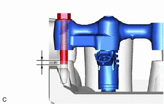 0.552,1.219 0.865,1.375 0.313,0.156 10 false *a
*a 2 to 3 threads
-
Install the 2 bolts by 2 to 3 threads.
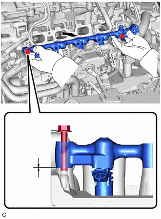
| *a | No Gap |
|
|
Push |
Push the fuel delivery pipe until it contacts the cylinder head sub-assembly.
- NOTICE:
-
Make sure that there is no gap between the fuel delivery pipe and cylinder head sub-assembly.
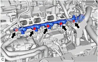
Install the fuel delivery pipe by uniformly tightening the 5 bolts in the order shown in the illustration.
- Torque:
- 29 N*m (296 kgf*cm, 21 ft.*lbf)
82124
4.CONNECT NO. 4 ENGINE WIRE
Connect the fuel pressure sensor (fuel delivery pipe) connector.
Connect the 4 fuel injector assembly connectors.
23100X
5.INSTALL FUEL (ENGINE ROOM SIDE) PUMP ASSEMBLY
6.PERFORM INITIALIZATION
Perform "Inspection After Repair" after replacing a fuel injector assembly.