BRAKE CONTROL / DYNAMIC CONTROL SYSTEMS BRAKE PEDAL STROKE SENSOR(for HV Model) INSTALLATION
PROCEDURE

 1.INSPECT AND ADJUST BRAKE PEDAL HEIGHT
89510D
2.INSTALL BRAKE PEDAL STROKE SENSOR ASSEMBLY
When installing a new brake pedal stroke sensor assembly:
- NOTICE:
-
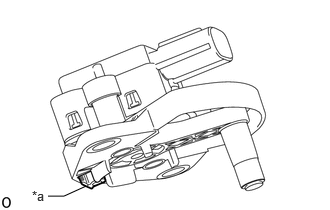 0.5,2.042 0.667,2.042 0.667,2.042 0.896,1.938 false 0.333,1.958 0.646,2.156 0.313,0.198 10 false *a
*a Locking Plate
-
Until the brake pedal stroke sensor assembly has been installed to the brake pedal support assembly with the nut, do not press in the brake pedal stroke sensor lever locking plate.
- HINT:
-
When the brake pedal stroke sensor assembly has been tightened to the specified torque, the locking plate will be released.

| *a | Brake Pedal Stroke Sensor Assembly Lever |
| *b | Brake Pedal Groove |
Install a new brake pedal stroke sensor assembly to the brake pedal support assembly with the 2 nuts.
- Torque:
- 8.5 N*m (87 kgf*cm, 75 in.*lbf)
- NOTICE:
- ·
Engage the brake pedal stroke sensor assembly lever with the brake pedal groove.
·Check that there is no foreign matter attached to the contact surface of the brake pedal stroke sensor assembly.
·Check that the tip of the brake pedal stroke sensor assembly lever is protruding from the brake pedal groove.
·Do not drop the brake pedal stroke sensor assembly.
·If the brake pedal stroke sensor assembly has been dropped, replace the brake pedal stroke sensor assembly with a new one.
Connect the connector.
When reusing the brake pedal stroke sensor assembly:
| *a | Brake Pedal Stroke Sensor Assembly Lever |
| *b | Brake Pedal Groove |
Install brake pedal stroke sensor assembly to the brake pedal support assembly with the 2 nuts.
- Torque:
- 8.5 N*m (87 kgf*cm, 75 in.*lbf)
- NOTICE:
- ·
Engage the brake pedal stroke sensor assembly lever with the brake pedal groove.
·Check that there is no foreign matter attached to the contact surface of the brake pedal stroke sensor assembly.
·Check that the tip of the brake pedal stroke sensor assembly lever is protruding from the brake pedal groove.
·Do not drop the brake pedal stroke sensor assembly.
·If the brake pedal stroke sensor assembly has been dropped, replace the brake pedal stroke sensor assembly with a new one.
Connect the connector.
55606
3.INSTALL NO. 1 INSTRUMENT PANEL UNDER COVER SUB-ASSEMBLY
4.CONNECT CABLE TO NEGATIVE AUXILIARY BATTERY TERMINAL
for 8ZR-FXE: Click hereGeneral>MAINTENANCE>8ZR-FXE AUXILIARY BATTERY>INSTALLATION202304,999999,_V1,_080956,_0392376,RM100000002ACL8,
for M20F-FXS, M20G-FXS: Click hereGeneral>MAINTENANCE>M20F-FXS, M20G-FXS AUXILIARY BATTERY>INSTALLATION202307,999999,_V1,_080956,_0611807,RM100000002CK9L,
5. PERFORM INITIALIZATION AND CALIBRATION
Perform linear solenoid valve offset learning, ABS holding solenoid valve learning, brake pedal stroke sensor assembly zero point calibration and system information memorization:
6.CHECK AND CLEAR DTC
7. INITIALIZATION AFTER RECONNECTING AUXILIARY BATTERY TERMINAL
- HINT:
-
When disconnecting and reconnecting the auxiliary battery, there is an automatic learning function that completes learning when the respective system is used.