RM3660EC _51 Engine / Hybrid System _080778 8ZR-FXE ENGINE CONTROL _0393982 SFI SYSTEM J

8ZR-FXE ENGINE CONTROL  SFI SYSTEM  Fuel Injector Circuit  


DESCRIPTION

The fuel injector assemblies are located in each intake port and inject fuel into the cylinders based on the signals from the ECM.

WIRING DIAGRAM
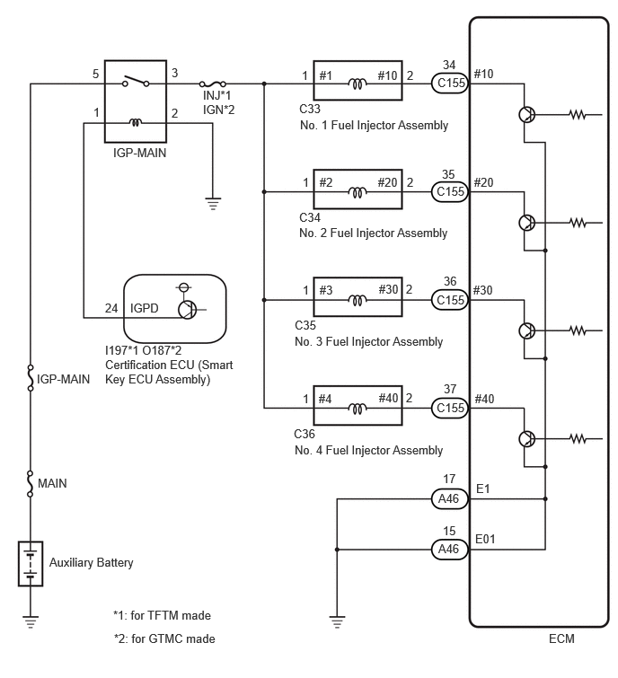
A520309E04
5.5,0.771 5.958,0.969 0.458,0.198 10 false #10 1.99,0.76 2.302,0.958 0.313,0.198 10 false 3 4.719,0.792 4.875,0.99 0.156,0.198 10 false 2 4.385,0.792 4.844,0.99 0.458,0.198 10 false #10 3.708,0.792 4.021,0.99 0.313,0.198 10 false #1 3.5,0.792 3.656,0.99 0.156,0.198 10 false 1 3.469,1.177 3.927,1.375 0.458,0.198 10 false C33 3.479,1.365 5.49,1.688 2.01,0.323 10 false No. 1 Fuel Injector Assembly 2.354,1.021 2.813,1.219 0.458,0.198 10 false INJ*1 1.313,1.688 2.688,1.885 1.375,0.198 10 false IGP-MAIN 0.427,4.313 1.167,4.583 0.74,0.271 10 false IGP-MAIN 0.438,5.521 1.813,5.719 1.375,0.198 10 false MAIN 0.573,6.438 1.719,6.781 1.146,0.344 10 false Auxiliary Battery 1.219,4.146 2.823,4.917 1.604,0.771 10 false Certification ECU (Smart Key ECU Assembly) 5.135,6.073 5.448,6.271 0.313,0.198 10 false 15 5.51,6.167 5.969,6.365 0.458,0.198 10 false E01 6.365,7.323 6.823,7.521 0.458,0.198 10 false ECM 3.469,2.438 3.927,2.635 0.458,0.198 10 false C34 3.469,2.615 5.365,2.938 1.896,0.323 10 false No. 2 Fuel Injector Assembly 3.51,2.031 3.667,2.229 0.156,0.198 10 false 1 3.708,2.031 4.021,2.229 0.313,0.198 10 false #2 4.385,2.031 4.844,2.229 0.458,0.198 10 false #20 4.719,2.031 4.875,2.229 0.156,0.198 10 false 2 5.125,1.938 5.438,2.135 0.313,0.198 10 false 35 5.5,2.031 5.958,2.229 0.458,0.198 10 false #20 5.146,3.177 5.458,3.375 0.313,0.198 10 false 36 5.49,3.281 5.948,3.479 0.458,0.198 10 false #30 4.396,3.271 4.854,3.469 0.458,0.198 10 false #30 4.708,3.271 4.865,3.469 0.156,0.198 10 false 2 3.708,3.281 4.021,3.479 0.313,0.198 10 false #3 3.51,3.281 3.74,3.542 0.229,0.26 10 false 1 3.417,3.688 3.875,3.885 0.458,0.198 10 false C35 3.417,3.875 5.417,4.146 2,0.271 10 false No. 3 Fuel Injector Assembly 3.406,4.948 3.865,5.146 0.458,0.198 10 false C36 3.417,5.135 5.417,5.458 2,0.323 10 false No. 4 Fuel Injector Assembly 3.51,4.542 3.667,4.74 0.156,0.198 10 false 1 4.708,4.531 4.865,4.729 0.156,0.198 10 false 2 3.698,4.542 4.01,4.74 0.313,0.198 10 false #4 4.396,4.531 4.854,4.729 0.458,0.198 10 false #40 5.146,4.427 5.458,4.625 0.313,0.198 10 false 37 5.51,4.542 5.969,4.74 0.458,0.198 10 false #40 5.135,0.667 5.448,0.865 0.313,0.198 10 false 34 1.073,0.771 1.385,0.969 0.313,0.198 10 false 5 1.083,1.219 1.396,1.417 0.313,0.198 10 false 1 1.99,1.229 2.302,1.427 0.313,0.198 10 false 2 5.083,6.281 5.542,6.479 0.458,0.198 10 false A46 5.083,5.698 5.542,5.896 0.458,0.198 10 false A46 5.135,5.469 5.448,5.667 0.313,0.198 10 false 17 5.521,5.583 5.833,5.781 0.313,0.198 10 false E1 5.063,4.646 5.677,4.844 0.615,0.198 10 false C155 5.063,3.396 5.677,3.594 0.615,0.198 10 false C155 5.063,2.135 5.677,2.333 0.615,0.198 10 false C155 5.073,0.875 5.688,1.073 0.615,0.198 10 false C155 1.219,3.979 2.292,4.198 1.073,0.219 10 false I197*1 O187*2 1.51,3.49 2.125,3.688 0.615,0.198 10 false IGPD 1.219,3.49 1.531,3.688 0.313,0.198 10 false 24 2.354,1.188 2.813,1.385 0.458,0.198 10 false IGN*2 1.323,7.323 2.771,7.688 1.448,0.365 10 false *2: for GTMC made 1.313,7.052 2.458,7.396 1.146,0.344 10 false *1: for TFTM made

CAUTION / NOTICE / HINT

NOTICE:

Inspect the fuses for circuits related to this system before performing the following procedure.


PROCEDURE
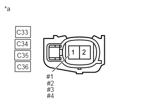
1.CHECK TERMINAL VOLTAGE (POWER SOURCE OF FUEL INJECTOR ASSEMBLY)
A431554C01
0.333,0.573 0.656,0.813 0.323,0.24 0.323,0.854 0.656,1.063 0.333,0.208 0.313,1.094 0.656,1.302 0.344,0.208 0.323,1.333 0.656,1.552 0.333,0.219 1.125,1.552 1.5,1.177 true 0.094,0.104 0.406,0.302 0.313,0.198 10 false *a 0.354,0.615 0.813,0.813 0.458,0.198 10 false C33 0.354,0.865 0.813,1.063 0.458,0.198 10 false C34 0.365,1.115 0.823,1.313 0.458,0.198 10 false C35 0.365,1.365 0.823,1.563 0.458,0.198 10 false C36 1,1.573 1.313,1.771 0.313,0.198 10 false #1 1.01,1.719 1.323,1.917 0.313,0.198 10 false #2 1.01,1.854 1.323,2.052 0.313,0.198 10 false #3 1.01,1.99 1.24,2.167 0.229,0.177 10 false #4
*a Front view of wire harness connector
(to Fuel Injector Assembly)


a.

Disconnect the fuel injector assembly connector.


b.

Turn the power switch on (IG).


c.

Measure the voltage according to the value(s) in the table below.

Standard Voltage:
Tester Connection Condition Specified Condition
C33-1 (#1) - Body ground Power switch on (IG) 11 to 14 V
C34-1 (#2) - Body ground Power switch on (IG) 11 to 14 V
C35-1 (#3) - Body ground Power switch on (IG) 11 to 14 V
C36-1 (#4) - Body ground Power switch on (IG) 11 to 14 V


Result:
Proceed to
OK
NG


OK

2.INSPECT FUEL INJECTOR ASSEMBLY (INJECTION AND VOLUME)

NG

4.CHECK HARNESS AND CONNECTOR (IGP-MAIN RELAY - FUEL INJECTOR ASSEMBLY)
2.INSPECT FUEL INJECTOR ASSEMBLY (INJECTION AND VOLUME)

Result:
Proceed to
OK
NG


OK

3.CHECK HARNESS AND CONNECTOR (FUEL INJECTOR ASSEMBLY - ECM)

NG

3.CHECK HARNESS AND CONNECTOR (FUEL INJECTOR ASSEMBLY - ECM)
a.

Disconnect the fuel injector assembly connector.


b.

Disconnect the ECM connector.


c.

Measure the resistance according to the value(s) in the table below.

Standard Resistance:
Tester Connection Condition Specified Condition
C33-2 (#10) - C155-34 (#10) Always Below 1 Ω
C34-2 (#20) - C155-35 (#20) Always Below 1 Ω
C35-2 (#30) - C155-36 (#30) Always Below 1 Ω
C36-2 (#40) - C155-37 (#40) Always Below 1 Ω
C33-2 (#10) or C155-34 (#10) - Body ground and other terminals Always 10 kΩ or higher
C34-2 (#20) or C155-35 (#20) - Body ground and other terminals Always 10 kΩ or higher
C35-2 (#30) or C155-36 (#30) - Body ground and other terminals Always 10 kΩ or higher
C36-2 (#40) or C155-37 (#40) - Body ground and other terminals Always 10 kΩ or higher


Result:
Proceed to
OK
NG


OK

NG

REPAIR OR REPLACE HARNESS OR CONNECTOR

4.CHECK HARNESS AND CONNECTOR (IGP-MAIN RELAY - FUEL INJECTOR ASSEMBLY)
a.

Disconnect the IGP-MAIN relay from No. 1 engine room relay block and No. 1 junction block assembly.


b.

Disconnect the fuel injector assembly connector.


c.

Measure the resistance according to the value(s) in the table below.

Standard Resistance:
Tester Connection Condition Specified Condition
3 (IGP-MAIN relay) - C33-1 (#1) Always Below 1 Ω
3 (IGP-MAIN relay) - C34-1 (#2) Always Below 1 Ω
3 (IGP-MAIN relay) - C35-1 (#3) Always Below 1 Ω
3 (IGP-MAIN relay) - C36-1 (#4) Always Below 1 Ω
3 (IGP-MAIN relay) or C33-1 (#1) - Body ground and other terminals Always 10 kΩ or higher
3 (IGP-MAIN relay) or C34-1 (#2) - Body ground and other terminals Always 10 kΩ or higher
3 (IGP-MAIN relay) or C35-1 (#3) - Body ground and other terminals Always 10 kΩ or higher
3 (IGP-MAIN relay) or C36-1 (#4) - Body ground and other terminals Always 10 kΩ or higher


HINT:

If a short is detected in any of the above circuits, there may be a malfunction in the circuit of a connected ECU.


Result:
Proceed to
OK
NG


OK

NG

REPAIR OR REPLACE HARNESS OR CONNECTOR