8ZR-FXE FUEL FUEL INJECTOR INSPECTION
PROCEDURE

 23250
1.INSPECT FUEL INJECTOR ASSEMBLY
23250
1.INSPECT FUEL INJECTOR ASSEMBLY
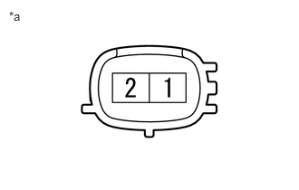
| *a | Component without harness connected
(Fuel Injector Assembly) |
Check the resistance.
Measure the resistance according to the value(s) in the table below.
- Standard Resistance:
Tester Connection Condition Specified Condition 1 - 2 20°C (68°F) 11.6 to 12.4 Ω
If the result is not as specified, replace the fuel injector assembly.
Check the operation.
- CAUTION:
-
Perform the inspection in a well-ventilated area.
-
Do not perform the inspection near an open flame.
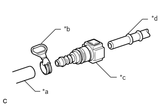
| *a | SST (Hose) |
| *b | SST (Hose Band) |
| *c | SST (Fuel Tube Connector) |
| *d | Fuel Pipe (Vehicle Side) |
Connect SST (fuel tube connector) to SST (hose) with SST (hose band), and then connect them to the fuel pipe (vehicle side).
- SST
- 09268-00010 (09268-00030)
09268-31015 (09268-41700, 95336-08070)
- NOTICE:
-
Make sure the SST (fuel tube connector) O-rings are not damaged and are free of foreign matter as they are used to seal the connections between SST (fuel tube connector) and the fuel pipe (vehicle side).
Apply a light coat of gasoline to a new O-ring, and then install the O-ring to the fuel injector assembly.
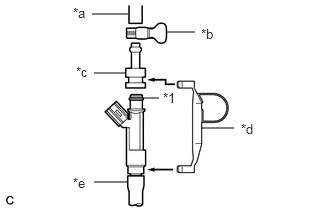
| *1 | O-ring |
| *a | SST (Hose) |
| *b | SST (Hose Band) |
| *c | SST (Adapter) |
| *d | SST (Clamp) |
| *e | Vinyl Tube |
Connect SST (adapter) and SST (hose) to the fuel injector assembly, and hold the fuel injector assembly and union with SST (clamp).
- SST
- 09268-31015 (09268-41110, 09268-41410, 09268-41700, 95336-08070)
Install a vinyl tube to the fuel injector assembly.
- CAUTION:
-
Install a suitable vinyl tube to the fuel injector assembly to prevent fuel from spraying.
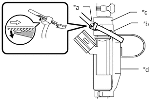
| *a | Lock |
| *b | SST (Tie Band) |
| *c | SST (Adapter) |
| *d | SST (Clamp) |
Tie SST (clamp) and SST (adapter) together with SST (tie band) as shown in the illustration.
- SST
- 09268-31015 (09268-41800)
- NOTICE:
- ·
As SST (tie band) does not completely prevent SST (clamp) from becoming loose, do not subject the parts to any impacts while using them.
·Before using SST (tie band), make sure that there is no wear, damage or cracks. If there are any abnormalities, replace SST (tie band).
- HINT:
-
When removing SST (tie band), disengage the lock.
Check that SST (clamp) and SST (adapter) cannot be easily separated.
Set the fuel injector assembly in a graduated cylinder.
Connect the GTS to the DLC3.
Turn the power switch on (IG).
- NOTICE:
-
Do not start the engine.
Turn the GTS on.
Enter the following menus: Powertrain / Engine / Active Test / Activate the Circuit Relay.
- Powertrain > Engine > Active Test
-
Tester Display Activate the Circuit Relay - 50004 372 38
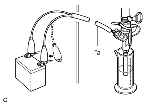
| *a | SST (EFI Inspection Wire H) |
Connect SST (EFI inspection wire H) to the fuel injector assembly and auxiliary battery for 15 seconds, and measure the injection volume with the graduated cylinder. Test each fuel injector assembly 2 or 3 times.
- SST
- 09842-30080
- Standard Injection Volume:
Auxiliary Battery Connection Condition Specified Condition Positive (+) auxiliary battery terminal - Negative (-) auxiliary battery terminal Per 15 seconds 60 to 73 cc (3.7 to 4.5 cu. in.)
- Difference between Each Fuel Injector Assembly:
13 cc (0.8 cu. in.) or less
- NOTICE:
- ·
Make sure that SST (EFI inspection wire H) is securely connected.
·Always switch the voltage on and off at the auxiliary battery side, not the fuel injector assembly side.
If the result is not as specified, replace the fuel injector assembly.
Check for leaks.
Disconnect SST (EFI inspection wire H) from the auxiliary battery and check for fuel leaks from the fuel injector assembly.
- Standard Fuel Drop:
1 drop or less per 20 minutes
If the result is not as specified, replace the fuel injector assembly.