HYBRID / BATTERY CONTROL PA10 HYBRID BATTERY SYSTEM(for LITHIUM-ION BATTERY) P1AFD00 Flying Capacitor Circuit Voltage Out of Range
DESCRIPTION
The battery ECU assembly monitors its internal operation and will store these DTCs when it detects an internal malfunction.
| DTC No. | Detection Item | DTC Detection Condition | Trouble Area | MIL | Warning Indicate | Note |
|---|---|---|---|---|---|---|
| P1AFD00 | Flying Capacitor Circuit Voltage Out of Range | ECU internal malfunction
(1 trip detection logic) |
·
Battery ECU assembly ·
HV battery |
Comes on | Master Warning:
Comes on |
SAE Code: P1AFD |
CONFIRMATION DRIVING PATTERN
- HINT:
- ·
After repair has been completed, clear the DTC and then check that the vehicle has returned to normal by performing the following All Readiness check procedure.
·When clearing the permanent DTCs, refer to the "CLEAR PERMANENT DTC" procedure.
Connect the GTS to the DLC3.
Turn the ignition switch to ON and turn the GTS on.
Clear the DTCs (even if no DTCs are stored, perform the clear DTC procedure).
Turn the ignition switch off and wait for 2 minutes or more.
Turn the ignition switch to ON and turn the GTS on.
With ignition switch ON and wait for 30 seconds or more.[*1]
- HINT:
-
[*1]: Normal judgment procedure.
-
The normal judgment procedure is used to complete DTC judgment and also used when clearing permanent DTCs.
Enter the following menus: Powertrain / HV Battery / Utility / All Readiness.
Check the DTC judgment result.
- HINT:
- ·
If the judgment result shows NORMAL, the system is normal.
·If the judgment result shows ABNORMAL, the system has a malfunction.
·If the judgment result shows INCOMPLETE, perform the normal judgment procedure again.
CAUTION / NOTICE / HINT
- CAUTION:
-
Refer to the precautions before inspecting high voltage circuit.
- NOTICE:
- ·
After the ignition switch is turned off, there may be a waiting time before disconnecting the negative (-) auxiliary battery terminal.
·When disconnecting and reconnecting the auxiliary battery
- HINT:
-
When disconnecting and reconnecting the auxiliary battery, there is an automatic learning function that completes learning when the respective system is used.
PROCEDURE
Check for DTCs.
- Powertrain > HV Battery > Trouble Codes
- 50001 398
- Result:
Result Proceed to "P1AFD00" only is output. A DTCs except "P1AFD00" are output. B
Turn the ignition switch off.
A
B
- CAUTION:
-
Be sure to wear insulated gloves and protective goggles.
Check that the service plug grip is not installed.
- NOTICE:
-
After removing the service plug grip, do not turn the ignition switch to ON (READY), unless instructed by the repair manual because this may cause a malfunction.
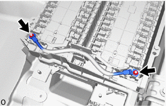
Check the connector connections and contact pressure of the relevant terminals for the HV supply stack sub-assembly.
- OK:
The connector is connected securely and there are no contact problems.
- Result:
Result Proceed to OK A Not connected securely The terminals are not damaged or corroded B Not connected securely The terminals are damaged or corroded C
A
B
C