HYBRID / BATTERY CONTROL BATTERY ECU(for LITHIUM-ION BATTERY) REMOVAL
CAUTION / NOTICE / HINT
The necessary procedures (adjustment, calibration, initialization or registration) that must be performed after parts are removed and installed, or replaced during battery ECU assembly removal/installation are shown below.
| Replaced Part or Performed Procedure | Necessary Procedure | Effect/Inoperative Function when Necessary Procedure not Performed | Link |
|---|---|---|---|
| Replacement of battery ECU assembly | Current sensor offset learning | DTCs are stored | ( 202304,999999,_51,_080773,_0599560,RM100000002B8MP_01_0296,) 202304,999999,_51,_080773,_0599560,RM100000002B8MP_01_0296,)
|
- CAUTION:
- ·
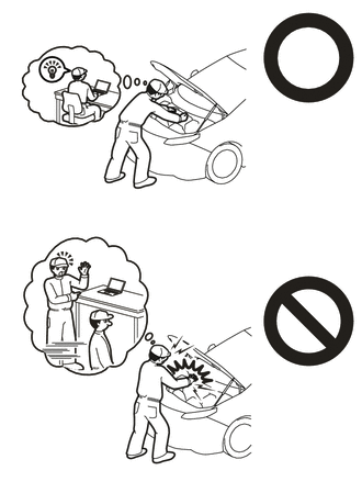
Orange wire harnesses and connectors indicate high-voltage circuits. To prevent electric shock, always follow the procedure described in the repair manual.
·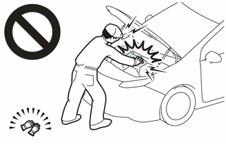
To prevent electric shock, wear insulated gloves when working on wire harnesses and components of the high voltage system.
- NOTICE:
- ·
The type of battery ECU assembly to be used varies depending on the vehicle model.
·If the wrong type of battery ECU assembly is installed, the power switch cannot be turned on (READY).
·After installing the battery ECU assembly, perform the following to check that the power switch can be turned on (READY).
-Turn the power switch on (READY).
-Turn the power switch off and wait for 30 seconds or more.
-Turn the power switch on (READY) again.
·This procedure includes the removal of small-head bolts. Refer to Small-Head Bolts of Basic Repair Hint to identify the small-head bolts.
·After turning the power switch off, waiting time may be required before disconnecting the cable from the negative (-) auxiliary battery terminal. Therefore, make sure to read the disconnecting the cable from the negative (-) auxiliary battery terminal notices before proceeding with work.
- HINT:
-
When the cable is disconnected / reconnected to the auxiliary battery terminal, systems temporarily stop operating. However, each system has a function that completes learning the first time the system is used.
Learning completes when vehicle is driven Effect/Inoperative Function when Necessary Procedure not Performed Necessary Procedure Link Front Camera System Drive the vehicle straight ahead at 15 km/h (9 mph) or more for 1 seconds or more. ( 202304,999999,_95,_139716,_0584193,RM1000000029F4C,)
PROCEDURE

 1. PRECAUTION
2. WHEN REPLACING BATTERY ECU ASSEMBLY
HV battery learning values are stored in the battery ECU assembly and ECM and are used to detect malfunctions and illuminate the hybrid battery indicator light in the combination meter assembly. When either of these ECUs is replaced, the new ECU receives the HV battery learning values from the other ECU and stores them.
- NOTICE:
- ·
Do not replace the battery ECU assembly and ECM at the same time as the HV battery learning values will be lost. However, if it is necessary to replace both ECUs at the same time, replace them by following the procedure below.
·Do not replace the battery ECU assembly or ECM with a used one from another vehicle.
Procedure when replacing both battery ECU assembly and ECM:
Disconnect the cable from the negative (-) auxiliary battery terminal.
Replace either ECU.
Connect the cable to the negative (-) auxiliary battery terminal.
Turn the power switch on (READY) and wait for 5 minutes or more.
Turn the power switch off and disconnect the cable from the negative (-) auxiliary battery terminal.
Replace the other ECU.
Connect the cable to the negative (-) auxiliary battery terminal.
Check that the power switch can be turned on (READY).
- HINT:
-
If the battery ECU assembly and ECM are replaced at the same time without following the above procedure, replace either of the ECUs with its original one and then replace it again by following the above procedure. If the correct procedure is not followed, perform the procedure again from the beginning.
G3834
3.REMOVE SERVICE PLUG GRIP
4.REMOVE CONNECTOR COVER ASSEMBLY
5.CHECK TERMINAL VOLTAGE
6.INSTALL CONNECTOR COVER ASSEMBLY
73350C
7.DISCONNECT REAR CENTER SEAT OUTER BELT ASSEMBLY
for Fold Down Seat Type:
8.REMOVE REAR SEAT CUSHION ASSEMBLY
for Fold Down Seat Type:
72693
9.REMOVE REAR SEAT CUSHION LOCK HOOK
for Fold Down Seat Type:
67918A
10.REMOVE REAR DOOR SCUFF PLATE LH
76974F
11.REMOVE REAR UNDER SIDE COVER LH
67917A
12.REMOVE REAR DOOR SCUFF PLATE RH
- HINT:
-
Use the same procedure as for the LH side.
76973F
13.REMOVE REAR UNDER SIDE COVER RH
- HINT:
-
Use the same procedure as for the LH side.
76971G
14.REMOVE REAR UNDER COVER
71033
15.REMOVE REAR SEAT CUSHION LEG SUB-ASSEMBLY
G92N4A
16.REMOVE NO. 1 HV BATTERY COVER PANEL RH
17.REMOVE UPPER NO. 1 HYBRID BATTERY COVER SUB-ASSEMBLY
- CAUTION:
-
Be sure to wear insulated gloves and protective goggles.
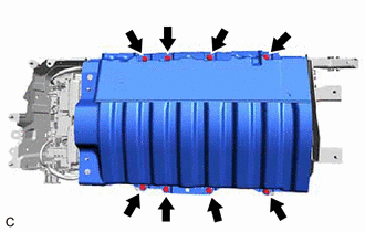
Remove the 8 bolts and upper No. 1 hybrid battery cover sub-assembly from the HV battery.
89890A
18.REMOVE BATTERY ECU ASSEMBLY
- CAUTION:
-
Be sure to wear insulated gloves and protective goggles.
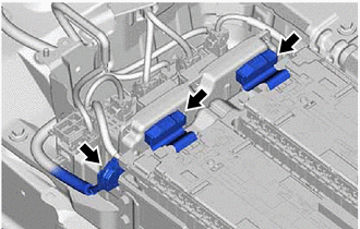
Disconnect the 3 battery ECU assembly connectors.
- NOTICE:
-
Insulate each disconnected high-voltage connector with insulating tape. Wrap the connector from the wire harness side to the end of the connector.
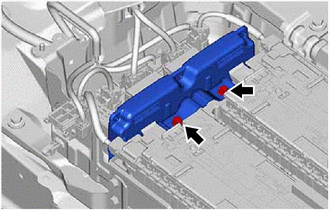
Using an 8 mm socket wrench, remove the 2 bolts and battery ECU assembly from the HV battery.
- NOTICE:
-
If the battery ECU assembly has been struck or dropped, replace it.