HYBRID / BATTERY CONTROL PA10 HYBRID BATTERY SYSTEM(for LITHIUM-ION BATTERY) P0ABF11 Hybrid/EV Battery Current Sensor "A" Circuit Short to Ground P0ABF15 Hybrid/EV Battery Current Sensor "A" Circuit Short to Auxiliary Battery or Open P0B0E11 Hybrid/EV Battery Current Sensor "B" Circuit Short to Ground P0B0E15 Hybrid/EV Battery Current Sensor "B" Circuit Short to Auxiliary Battery or Open P1CBB12 Hybrid/EV Battery Current Sensor Power Supply Circuit Short to Auxiliary Battery P1CBB14 Hybrid/EV Battery Current Sensor Power Supply Circuit Short to Ground or Open
DESCRIPTION
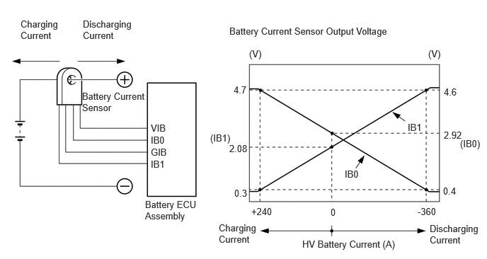
A battery current sensor, which is mounted on the positive cable side of each HV battery junction block assembly, detects the current flowing to or from the battery pack. The battery current sensor sends a voltage, which varies between 0 and 5 V in proportion to the amperage, to the IB0 terminal of the battery ECU assembly. Similarly, it sends a voltage, which varies between 0 and 5 V in inverse proportion to the amperage, to the IB1 terminal of the battery ECU assembly. When the voltage at the IB0 terminal is below 2.92 V and the voltage at the IB1 terminal is above 2.08 V, this indicates that the HV battery is being discharged. Additionally, Meanwhile, when the voltage at of the IB0 terminal is above 2.92 V and the voltage at of the IB1 terminal is below 2.08 V, this indicates that the HV battery is being charged. The battery ECU assembly determines the charging and discharging amount of the HV battery based on the voltages input to the IB0 terminal and IB1 terminal and calculates the SOC of the HV battery through the accumulated amperage.
| DTC No. | Detection Item | DTC Detection Condition | Trouble Area | MIL | Warning Indicate | Note |
|---|---|---|---|---|---|---|
| P0ABF11 | Hybrid/EV Battery Current Sensor "A" Circuit Short to Ground | The battery current sensor output voltage (IB0) is excessively low.
(1 trip detection logic) |
·
HV battery junction block assembly ·
Battery ECU assembly ·
Wire harness or connector |
Comes on | Master warning:
Comes on |
SAE Code: P0AC1 |
| P0ABF15 | Hybrid/EV Battery Current Sensor "A" Circuit Short to Auxiliary Battery or Open | The battery current sensor output voltage (IB0) is excessively high.
(1 trip detection logic) |
·
HV battery junction block assembly ·
Battery ECU assembly ·
Wire harness or connector |
Comes on | Master warning:
Comes on |
SAE Code: P0AC2 |
| P0B0E11 | Hybrid/EV Battery Current Sensor "B" Circuit Short to Ground | The battery current sensor output voltage (IB1) is excessively low.
(1 trip detection logic) |
·
HV battery junction block assembly ·
Battery ECU assembly ·
Wire harness or connector |
Comes on | Master warning:
Comes on |
SAE Code: P0B10 |
| P0B0E15 | Hybrid/EV Battery Current Sensor "B" Circuit Short to Auxiliary Battery or Open | The battery current sensor output voltage (IB1) is excessively high.
(1 trip detection logic) |
·
HV battery junction block assembly ·
Battery ECU assembly ·
Wire harness or connector |
Comes on | Master warning:
Comes on |
SAE Code: P0B11 |
| P1CBB12 | Hybrid/EV Battery Current Sensor Power Supply Circuit Short to Auxiliary Battery | Power source voltage (VIB) of the battery current sensor is excessively high.
(1 trip detection logic) |
·
HV battery junction block assembly ·
Battery ECU assembly ·
Wire harness or connector |
Comes on | Master warning:
Comes on |
SAE Code: P1CBD |
| P1CBB14 | Hybrid/EV Battery Current Sensor Power Supply Circuit Short to Ground or Open | Power source voltage (VIB) of the battery current sensor is excessively low.
(1 trip detection logic) |
·
HV battery junction block assembly ·
Battery ECU assembly ·
Wire harness or connector |
Comes on | Master warning:
Comes on |
SAE Code: P1CBC |
CONFIRMATION DRIVING PATTERN
- HINT:
- ·
After repair has been completed, clear the DTC and then check that the vehicle has returned to normal by performing the following All Readiness check procedure.
·When clearing the permanent DTCs, refer to the "CLEAR PERMANENT DTC" procedure.
Connect the GTS to the DLC3.
Turn the ignition switch to ON and turn the GTS on.
Clear the DTCs (even if no DTCs are stored, perform the clear DTC procedure).
Turn the ignition switch off and wait for 2 minutes or more.
Turn the ignition switch to ON and turn the GTS on.
With ignition switch ON and wait for 5 seconds or more.[*1]
- HINT:
-
[*1]: Normal judgment procedure.
-
The normal judgment procedure is used to complete DTC judgment and also used when clearing permanent DTCs.
Enter the following menus: Powertrain / HV Battery / Utility / All Readiness.
Check the DTC judgment result.
- HINT:
- ·
If the judgment result shows NORMAL, the system is normal.
·If the judgment result shows ABNORMAL, the system has a malfunction.
·If the judgment result shows INCOMPLETE, perform the normal judgment procedure again.
WIRING DIAGRAM
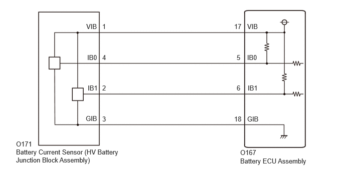
Refer to the wiring diagram for the ECU Power Source Circuit.
CAUTION / NOTICE / HINT
- CAUTION:
-
Refer to the precautions before inspecting high voltage circuit.
- NOTICE:
- ·
After the ignition switch is turned off, there may be a waiting time before disconnecting the negative (-) auxiliary battery terminal.
·When disconnecting and reconnecting the auxiliary battery
- HINT:
-
When disconnecting and reconnecting the auxiliary battery, there is an automatic learning function that completes learning when the respective system is used.
PROCEDURE
Check for DTCs.
- Powertrain > HV Battery > Trouble Codes
- 50001 398
- Powertrain > Hybrid Control > Trouble Codes
- 50001 397
- Result:
Result Proceed to "P0ABF11, P0ABF15, P0B0E11, P0B0E15, P1CBB12 or P1CBB14" only is output, or DTCs except the ones in the table below are also output. A DTCs of hybrid battery system in the table below are output. B DTCs of hybrid control system in the table below are output. C
| System | Relevant DTC | |
|---|---|---|
| Hybrid battery system | P060A47 | Hybrid/EV Battery Energy Control Module Monitoring Processor Watchdog / Safety MCU Failure |
| P060B49 | Hybrid/EV Battery Energy Control Module A/D Processing Internal Electronic Failure | |
| P060687 | Hybrid/EV Battery Energy Control Module Processor to Monitoring Processor Missing Message | |
| Hybrid control system | P0A1F94 | Hybrid/EV Battery Energy Control Module Unexpected Operation |
Turn the ignition switch off.
A
B
C
- CAUTION:
-
Be sure to wear insulated gloves and protective goggles.
Check that the service plug grip is not installed.
- NOTICE:
-
After removing the service plug grip, do not turn the ignition switch to ON (READY), unless instructed by the repair manual because this may cause a malfunction.
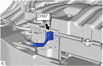
Disconnect the battery ECU assembly connector.
- NOTICE:
-
Before disconnecting the connector, check that it is not loose or disconnected.
Connect the cable to the negative (-) auxiliary battery terminal.
Turn the ignition switch to ON.
Measure the voltage according to the value(s) in the table below.
- Standard Voltage:
Tester Connection Condition Specified Condition O167-12 (IGCT) - O167-10 (GND) Ignition switch ON 11 to 14 V
- NOTICE:
- ·
Turning the ignition switch to ON with the service plug grip removed causes other DTCs to be stored. Clear the DTCs after performing this inspection.
·If the ignition switch is turned to ON with the connectors disconnected, other DTCs will be stored. Be sure to clear the DTCs after the inspection.
- HINT:
-
As there might be an intermittent malfunction, inspect the following items even if the measured voltage is as specified.
- ·
Installation condition of fuse(s) (before removing fuse(s)) (IG circuit)
·Fuse condition (before and after removing fuse(s)) (IG circuit)
·Connection condition of connectors (IG circuit)
·Wire harness condition (IG circuit)
·Wire harness condition (GND circuit)
Turn the ignition switch off.
Disconnect the cable from the negative (-) auxiliary battery terminal.
Reconnect the battery ECU assembly connector.
- Result:
Proceed to OK NG
OK
NG
- CAUTION:
-
Be sure to wear insulated gloves and protective goggles.
Check that the service plug grip is not installed.
- NOTICE:
-
After removing the service plug grip, do not turn the ignition switch to ON (READY), unless instructed by the repair manual because this may cause a malfunction.
Disconnect the battery ECU assembly connector.
- NOTICE:
-
Before disconnecting the connector, check that it is not loose or disconnected.
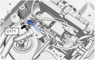
Disconnect the HV battery junction block assembly connector.
- NOTICE:
-
Before disconnecting the connector, check that it is not loose or disconnected.
Measure the resistance according to the value (s) in the tables below.
- Standard Resistance (Check for Open):
Tester Connection Condition Specified Condition O167-6 (IB1) - O171-2 (IB1) Ignition switch off Below 1 Ω O167-18 (GIB) - O171-3 (GIB) Ignition switch off Below 1 Ω O167-5 (IB0) - O171-4 (IB0) Ignition switch off Below 1 Ω O167-17 (VIB) - O171-1 (VIB) Ignition switch off Below 1 Ω
- Standard Resistance (Check for Short):
Tester Connection Condition Specified Condition O167-6 (IB1) or O171-2 (IB1) - Body ground and other terminals Ignition switch off 10 kΩ or higher O167-18 (GIB) or O171-3 (GIB) - Body ground and other terminals Ignition switch off 10 kΩ or higher O167-5 (IB0) or O171-4 (IB0) - Body ground and other terminals Ignition switch off 10 kΩ or higher O167-17 (VIB) or O171-1 (VIB) - Body ground and other terminals Ignition switch off 10 kΩ or higher
Reconnect the HV battery junction block assembly connector.
Reconnect the battery ECU assembly connector.
- Result:
Proceed to OK NG
OK
NG
- CAUTION:
-
Be sure to wear insulated gloves and protective goggles.
Check that the service plug grip is not installed.
- NOTICE:
-
After removing the service plug grip, do not turn the ignition switch to ON (READY), unless instructed by the repair manual because this may cause a malfunction.
Connect the cable to the negative (-) auxiliary battery terminal.
Turn the ignition switch to ON.
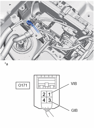
| *a | Component with harness connected
(HV Battery Junction Block Assembly (Battery Current Sensor)) |
Measure the voltage according to the value(s) in the table below.
- Standard Voltage:
Tester Connection Condition Specified Condition O171-1 (VIB) - O171-3 (GIB) Ignition switch ON 4.5 to 5.5 V
- NOTICE:
-
Turning the ignition switch to ON with the service plug grip removed causes other DTCs to be stored. Clear the DTCs after performing this inspection.
Turn the ignition switch off.
Disconnect the cable from the negative (-) auxiliary battery terminal.
- Result:
Proceed to OK NG
OK
NG
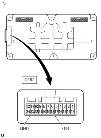
| *a | Component without harness connected
(Battery ECU Assembly) |
Measure the resistance according to the value (s) in the tables below.
- Standard Resistance:
Tester Connection Condition Specified Condition O167-10 (GND) - O167-18 (GIB) Ignition switch off Below 1 Ω
Install the battery ECU assembly.
- Result:
Proceed to OK NG
OK
NG
- CAUTION:
-
Be sure to wear insulated gloves and protective goggles.
Check that the service plug grip is not installed.
- NOTICE:
-
After removing the service plug grip, do not turn the ignition switch to ON (READY), unless instructed by the repair manual because this may cause a malfunction.
Connect the cable to the negative (-) auxiliary battery terminal.
Turn the ignition switch to ON.
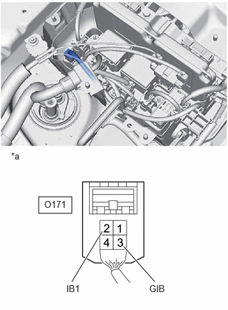
| *a | Component with harness connected
(HV Battery Junction Block Assembly (Battery Current Sensor)) |
Measure the voltage according to the value(s) in the table below.
- Standard Voltage:
Tester Connection Condition Specified Condition O171-2 (IB1) - O171-3 (GIB) Ignition switch ON 2.02 to 2.14 V
- NOTICE:
-
Turning the ignition switch to ON with the service plug grip removed causes other DTCs to be stored. Clear the DTCs after performing this inspection.
Turn the ignition switch off.
Disconnect the cable from the negative (-) auxiliary battery terminal.
- Result:
Proceed to OK NG
OK
NG
- CAUTION:
-
Be sure to wear insulated gloves and protective goggles.
Check that the service plug grip is not installed.
- NOTICE:
-
After removing the service plug grip, do not turn the ignition switch to ON (READY), unless instructed by the repair manual because this may cause a malfunction.
Connect the cable to the negative (-) auxiliary battery terminal.
Turn the ignition switch to ON.
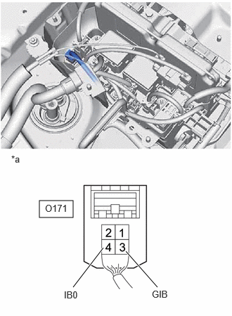
| *a | Component with harness connected
(HV Battery Junction Block Assembly (Battery Current Sensor)) |
Measure the voltage according to the value(s) in the table below.
- Standard Voltage:
Tester Connection Condition Specified Condition O171-4 (IB0) - O171-3 (GIB) Ignition switch ON 2.86 to 2.98 V
- NOTICE:
-
Turning the ignition switch to ON with the service plug grip removed causes other DTCs to be stored. Clear the DTCs after performing this inspection.
Turn the ignition switch off.
Disconnect the cable from the negative (-) auxiliary battery terminal.
- Result:
Proceed to OK NG
OK
NG
- CAUTION:
-
Be sure to wear insulated gloves and protective goggles.
Check that the service plug grip is not installed.
- NOTICE:
-
After removing the service plug grip, do not turn the ignition switch to ON (READY), unless instructed by the repair manual because this may cause a malfunction.
Connect the cable to the negative (-) auxiliary battery terminal.
Turn the ignition switch to ON.
| *a | Component with harness connected
(HV Battery Junction Block Assembly (Battery Current Sensor)) |
Measure the voltage according to the value(s) in the table below.
| Tester Connection | Condition |
|---|---|
| O171-4 (IB0) - O171-3 (GIB) | Ignition switch ON |
- NOTICE:
-
Turning the ignition switch to ON with the service plug grip removed causes other DTCs to be stored. Clear the DTCs after performing this inspection.
Turn the ignition switch off.
Disconnect the cable from the negative (-) auxiliary battery terminal.
- Result:
Result Proceed to 0.3 to 4.7 V A Below 0.3 V B More than 4.7 V C
A
B
C
- CAUTION:
-
Be sure to wear insulated gloves and protective goggles.
Check that the service plug grip is not installed.
- NOTICE:
-
After removing the service plug grip, do not turn the ignition switch to ON (READY), unless instructed by the repair manual because this may cause a malfunction.
Disconnect the battery current sensor connector from the HV battery junction block assembly.
- NOTICE:
-
Before disconnecting the connector, check that it is not loose or disconnected.
Connect the cable to the negative (-) auxiliary battery terminal.
Turn the ignition switch to ON.
Measure the voltage according to the value(s) in the table below.
- Standard Voltage:
Tester Connection Condition Specified Condition O171-4 (IB0) - O171-3 (GIB) Ignition switch ON 4.5 to 5.5 V
- NOTICE:
- ·
Turning the ignition switch to ON with the service plug grip removed causes other DTCs to be stored. Clear the DTCs after performing this inspection.
·If the ignition switch is turned to ON with the connectors disconnected, other DTCs will be stored. Be sure to clear the DTCs after the inspection.
Turn the ignition switch off.
Disconnect the cable from the negative (-) auxiliary battery terminal.
Reconnect the battery current sensor connector to the HV battery junction block assembly.
- Result:
Proceed to OK NG
OK
NG
- CAUTION:
-
Be sure to wear insulated gloves and protective goggles.
Check that the service plug grip is not installed.
- NOTICE:
-
After removing the service plug grip, do not turn the ignition switch to ON (READY), unless instructed by the repair manual because this may cause a malfunction.
Disconnect the battery current sensor connector from the HV battery junction block assembly.
- NOTICE:
-
Before disconnecting the connector, check that it is not loose or disconnected.
Measure the resistance according to the value(s) in the tables below.
- Standard Resistance:
Tester Connection Condition Specified Condition O171-1 (VIB) - O171-4 (IB0) Ignition switch off 10 kΩ or higher
- NOTICE:
-
When taking a measurement with a tester, do not apply excessive force to the tester probe to avoid damaging the holder.
Reconnect the battery current sensor connector to the HV battery junction block assembly.
- Result:
Proceed to OK NG
OK
NG
- CAUTION:
-
Be sure to wear insulated gloves and protective goggles.
Check that the service plug grip is not installed.
- NOTICE:
-
After removing the service plug grip, do not turn the ignition switch to ON (READY), unless instructed by the repair manual because this may cause a malfunction.
Connect the cable to the negative (-) auxiliary battery terminal.
Turn the ignition switch to ON.
| *a | Component with harness connected
(HV Battery Junction Block Assembly (Battery Current Sensor)) |
Measure the voltage according to the value(s) in the table below.
- Standard Voltage:
Tester Connection Condition O171-2 (IB1) - O171-3 (GIB) Ignition switch ON
- NOTICE:
-
Turning the ignition switch to ON with the service plug grip removed causes other DTCs to be stored. Clear the DTCs after performing this inspection.
Turn the ignition switch off.
Disconnect the cable from the negative (-) auxiliary battery terminal.
- Result:
Result Proceed to 0.3 to 4.7 V A Below 0.3 V B More than 4.7 V C
A
B
C
- CAUTION:
-
Be sure to wear insulated gloves and protective goggles.
Check that the service plug grip is not installed.
- NOTICE:
-
After removing the service plug grip, do not turn the ignition switch to ON (READY), unless instructed by the repair manual because this may cause a malfunction.
Disconnect the battery current sensor connector from the HV battery junction block assembly.
- NOTICE:
-
Before disconnecting the connector, check that it is not loose or disconnected.
Connect the cable to the negative (-) auxiliary battery terminal.
Turn the ignition switch to ON.
Measure the voltage according to the value(s) in the table below.
- Standard Voltage:
Tester Connection Condition Specified Condition O171-2 (IB1) - O171-3 (GIB) Ignition switch ON 4.6 to 5.4 V
- NOTICE:
- ·
Turning the ignition switch to ON with the service plug grip removed causes other DTCs to be stored. Clear the DTCs after performing this inspection.
·If the ignition switch is turned to ON with the connectors disconnected, other DTCs will be stored. Be sure to clear the DTCs after the inspection.
Turn the ignition switch off.
Disconnect the cable from the negative (-) auxiliary battery terminal.
Reconnect the battery current sensor connector to the HV battery junction block assembly.
- Result:
Proceed to OK NG
OK
NG
- CAUTION:
-
Be sure to wear insulated gloves and protective goggles.
Check that the service plug grip is not installed.
- NOTICE:
-
After removing the service plug grip, do not turn the ignition switch to ON (READY), unless instructed by the repair manual because this may cause a malfunction.
Disconnect the battery current sensor connector from the HV battery junction block assembly.
- NOTICE:
-
Before disconnecting the connector, check that it is not loose or disconnected.
Connect the cable to the negative (-) auxiliary battery terminal.
Turn the ignition switch to ON.
Measure the voltage according to the value(s) in the table below.
- Standard Voltage:
Tester Connection Condition Specified Condition O171-1 (VIB) - O171-3 (GIB) Ignition switch ON 4.6 to 5.4 V
- NOTICE:
- ·
Turning the ignition switch to ON with the service plug grip removed causes other DTCs to be stored. Clear the DTCs after performing this inspection.
·If the ignition switch is turned to ON with the connectors disconnected, other DTCs will be stored. Be sure to clear the DTCs after the inspection.
Turn the ignition switch off.
Disconnect the cable from the negative (-) auxiliary battery terminal.
Reconnect the battery current sensor connector to the HV battery junction block assembly.
- Result:
Proceed to OK NG
OK
NG
- CAUTION:
-
Be sure to wear insulated gloves and protective goggles.
Check that the service plug grip is not installed.
- NOTICE:
-
After removing the service plug grip, do not turn the ignition switch to ON (READY), unless instructed by the repair manual because this may cause a malfunction.
Disconnect the battery current sensor connector from the HV battery junction block assembly.
- NOTICE:
-
Before disconnecting the connector, check that it is not loose or disconnected.
Measure the resistance according to the value (s) in the tables below.
- Standard Resistance:
Tester Connection Condition Specified Condition O171-1 (VIB) - O171-2 (IB1) Ignition switch off 10 kΩ or higher
- NOTICE:
-
When taking a measurement with a tester, do not apply excessive force to the tester probe to avoid damaging the holder.
Reconnect the battery current sensor connector from the HV battery junction block assembly.
- Result:
Proceed to OK NG
OK
NG