HYBRID / BATTERY CONTROL MOTOR GENERATOR CONTROL SYSTEM(for LITHIUM-ION BATTERY) P034000 Camshaft Position Sensor "A" Circuit Bank 1 or Single Sensor P034031 Camshaft Position Sensor "A" Circuit Bank 1 or Single Sensor No Signal
DESCRIPTION
If the cam position signal pulse sent from the ECM via a direct line is abnormal, the motor generator control ECU (MG ECU) (built into the inverter with converter assembly) stores DTC P034000 or P034031.
| DTC No. | Detection Item | DTC Detection Condition | Trouble Area | MIL | Warning Indicate | Note |
|---|---|---|---|---|---|---|
| P034000 | Camshaft Position Sensor "A" Circuit Bank 1 or Single Sensor | GI signal (camshaft position sensor) is not input for 2 seconds or more while the engine is running*
(1 trip detection logic) |
·
SFI system ·
Inverter with converter assembly ·
ECM ·
Wire harness or connector |
Does not come on | Master Warning:
Comes on |
SAE Code:
P0340 |
| P034031 | Camshaft Position Sensor "A" Circuit Bank 1 or Single Sensor No Signal | GI signal (camshaft position sensor) is not input for 2 seconds or more while the engine is running*
(1 trip detection logic) |
·
SFI system ·
Inverter with converter assembly ·
ECM ·
Wire harness or connector |
Does not come on | Master Warning:
Comes on |
SAE Code:
P0340 |
- HINT:
-
*: When this DTC is stored, vibration may occur when the engine is stopped.
CONFIRMATION DRIVING PATTERN
- HINT:
-
After repair has been completed, clear the DTC and then check that the vehicle has returned to normal by performing the following All Readiness check procedure.
Clear the DTCs (even if no DTCs are stored, perform the clear DTC procedure).
Turn the ignition switch off and wait for 2 minutes or more.
Turn the ignition switch to ON (READY).
With the vehicle stopped, move the shift lever to P.
Depress the accelerator pedal to start the engine.
Depress the accelerator pedal and maintain the engine speed at 1000 rpm or more for 5 seconds or more.
- NOTICE:
-
As the state of charge of the HV battery may be low after driving in fail-safe mode, it will automatically be charged for 5 to 10 minutes with ignition switch ON (READY) after repairs have been performed.
Enter the following menus: Powertrain / Motor Generator / Utility / All Readiness.
Check the DTC judgment result.
- HINT:
- ·
If the judgment result shows NORMAL, the system is normal.
·If the judgment result shows ABNORMAL, the system has a malfunction.
·If the judgment result shows INCOMPLETE, perform driving pattern again.
WIRING DIAGRAM
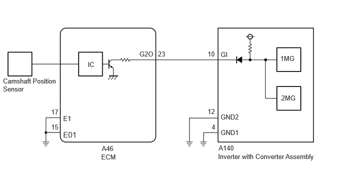
CAUTION / NOTICE / HINT
- CAUTION:
-
Refer to the precautions before inspecting high voltage circuit.
- NOTICE:
- ·
After the ignition switch is turned off, there may be a waiting time before disconnecting the negative (-) auxiliary battery terminal.
·When disconnecting and reconnecting the auxiliary battery.
- HINT:
-
When disconnecting and reconnecting the auxiliary battery, there is an automatic learning function that completes learning when the respective system is used.
- HINT:
-
P034000 or P034031 may be stored due to a malfunction which also causes the DTCs in the table below to be stored. In this case, first troubleshoot the output DTCs in the table below. Then, perform a test to attempt to reproduce the problems, and check that no DTCs are output.
Relevant DTC P06B01C Generator Control Module Position Sensor REF Power Source Circuit Voltage Out of Range P06D61C Generator Control Module Offset Power Circuit Voltage Out of Range P0A1B1F Generator Control Module Circuit Intermittent P1C2B49 Drive Motor "A" Control Module A/D Converter Circuit Internal Electronic Failure P1C2B1C Drive Motor "A" Control Module A/D Converter Circuit Voltage Out of Range P1CAD49 Drive Motor "A" Position Sensor Internal Electronic Failure P1CB038 Drive Motor "A" Position Sensor REF Signal Frequency Incorrect P313487 Communication Error from Drive Motor "A" to Generator Missing Message P313483 Communication Error from Drive Motor "A" to Generator Value of Signal Protection Calculation Incorrect P313486 Communication Error from Drive Motor "A" to Generator Signal Invalid
PROCEDURE
Check for DTCs.
- Powertrain > Engine > Trouble Codes
- 50001 372
- Result:
Result Proceed to SFI system DTCs are not output. A Any of the following DTCs are also output. B
| Relevant DTC | |
|---|---|
| P034011 | Camshaft Position Sensor "A" Bank 1 or Single Sensor Circuit Short to Ground |
| P034015 | Camshaft Position Sensor "A" Bank 1 or Single Sensor Circuit Short to Battery or Open |
| P03402A | Camshaft Position Sensor "A" Bank 1 or Single Sensor Signal Stuck in Range |
| P034031 | Camshaft Position Sensor "A" Bank 1 or Single Sensor No Signal |
Turn the ignition switch off.
A
B
- Result:
Result Proceed to OK A NG (The connector is not connected securely.) B NG (The terminals are not making secure contact or are deformed, or water or foreign matter exists in the connector.) C
A
B
C
- Result:
Proceed to OK NG
OK
NG
- CAUTION:
-
Be sure to wear insulated gloves.
Check that the service plug grip is not installed.
- NOTICE:
-
After removing the service plug grip, do not turn the ignition switch to ON (READY), unless instructed by the repair manual because this may cause a malfunction.
Disconnect the inverter with converter assembly connector.
Disconnect the ECM connector.
Connect the cable to the negative (-) auxiliary battery terminal.
Turn the ignition switch to ON.
Measure the voltage according to the value(s) in the table below.
- Standard Voltage:
Tester Connection Condition Specified Condition A140-10 (GI) - Body ground Ignition switch ON Below 1 V
- NOTICE:
-
Turning the ignition switch to ON with the inverter with converter assembly connector and ECM connector disconnected causes other DTCs to be stored. Clear the DTCs after performing this inspection.
Turn the ignition switch off.
Measure the resistance according to the value(s) in the table below.
- Standard Resistance (Check for Open):
Tester Connection Condition Specified Condition A140-10 (GI) - A46-23 (G2O) Ignition switch off Below 1 Ω
- Standard Resistance (Check for Short):
Tester Connection Condition Specified Condition A140-10 (GI) or A46-23 (G2O) - Body ground and other terminals Ignition switch off 10 kΩ or higher
Disconnect the cable from the negative (-) auxiliary battery terminal.
Reconnect the ECM connector.
Reconnect the inverter with converter assembly connector.
- Result:
Proceed to OK NG
OK
NG
Disconnect the ECM connector.
Measure the resistance according to the value(s) in the table below.
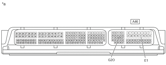
| *a | Component without harness connected
(ECM) |
- | - |
- Standard Resistance:
Tester Connection Condition Specified Condition A46-23 (G2O) - A46-17 (E1) Ignition switch off 10 kΩ or higher
Reconnect the ECM connector.
- Result:
Proceed to OK NG
OK
NG