HYBRID / BATTERY CONTROL 8ZR-FXE INVERTER WITH CONVERTER REMOVAL
CAUTION / NOTICE / HINT
The necessary procedures (adjustment, calibration, initialization or registration) that must be performed after parts are removed and installed, or replaced during inverter with converter assembly removal/installation are shown below.
| Replaced Part or Performed Procedure | Necessary Procedure | Effect/Inoperative Function when Necessary Procedure not Performed | Link |
|---|---|---|---|
| Replacement of inverter with converter assembly | ECU configuration | - | ( 202304,999999,_V1,_143216,_0598316,RM100000002B3MK,) 202304,999999,_V1,_143216,_0598316,RM100000002B3MK,)
|
| Resolver learning | ·
DTCs are stored ·
Slight vibration at a vehicle speed of 5 km/h (3 mph) or less ·
Shock or vibration during acceleration |
(202304,999999,_51,_080773,_0600292,RM100000002BBW3,)
|
- CAUTION:
- ·
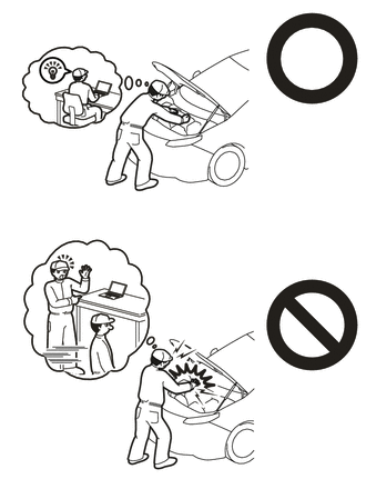
Orange wire harnesses and connectors indicate high-voltage circuits. To prevent electric shock, always follow the procedure described in the repair manual.
·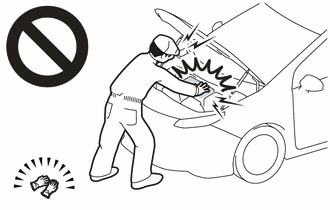
To prevent electric shock, wear insulated gloves when working on wire harnesses and components of the high voltage system.
- NOTICE:
-
After turning the power switch off, waiting time may be required before disconnecting the cable from the negative (-) auxiliary battery terminal. Therefore, make sure to read the disconnecting the cable from the negative (-) auxiliary battery terminal notices before proceeding with work.
- HINT:
-
When the cable is disconnected / reconnected to the auxiliary battery terminal, systems temporarily stop operating. However, each system has a function that completes learning the first time the system is used.
Items for which learning is completed by driving the vehicle Effect/Inoperative Function when Necessary Procedure not Performed Necessary Procedure Link Front Camera System Drive the vehicle straight ahead at 15 km/h (9 mph) or more for 1 seconds or more. ( 202304,999999,_95,_139716,_0584193,RM1000000029F4C,)
PROCEDURE

 1. PRECAUTION
89661
2.REMOVE ECM
G3834
3.REMOVE SERVICE PLUG GRIP
4.DRAIN COOLANT (for Inverter)
74404A
5.REMOVE BATTERY CLAMP SUB-ASSEMBLY
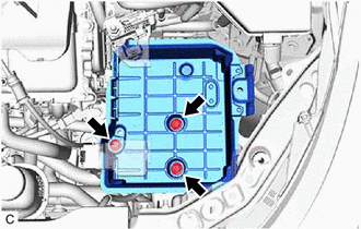
Remove the 3 bolts and battery clamp sub-assembly from the vehicle.
6.REMOVE CONNECTOR COVER ASSEMBLY
- CAUTION:
-
Be sure to wear insulated gloves.
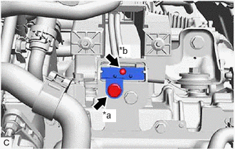
| *a | Bolt (A) |
| *b | Bolt (B) |
Remove the bolt (A).
Using a T20 "TORX" socket wrench, remove the bolt (B) and connector cover assembly from the inverter with converter assembly.
- NOTICE:
- ·
Do not touch the connector cover assembly waterproof seal.
·Do not allow any foreign matter or water to enter the inverter with converter assembly.
7.CHECK TERMINAL VOLTAGE
- CAUTION:
-
Be sure to wear insulated gloves.
Using a voltmeter, measure the voltage between the terminals of the 2 phase connectors.
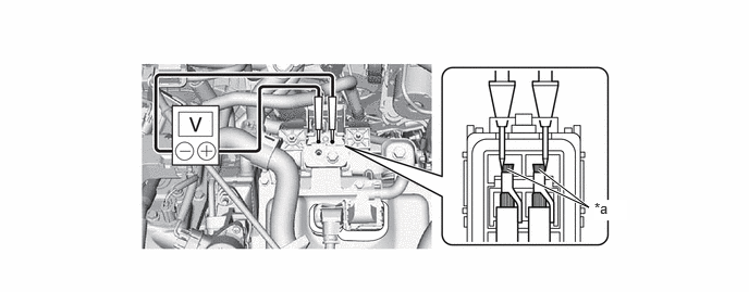
| *a | Terminal | - | - |
- Standard Voltage:
0 V
- NOTICE:
-
Do not allow any foreign matter or water to enter the inverter with converter assembly.
- HINT:
- ·
Use a measuring range of DC 750 V or more on the voltmeter.
·Perform the measurement while holding the tips of the tester probes against the terminals as shown in the illustration.
8.TEMPORARILY INSTALL CONNECTOR COVER ASSEMBLY
- CAUTION:
-
Be sure to wear insulated gloves.
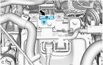
Temporarily install the connector cover assembly to the inverter with converter assembly.
Using a T20 "TORX" socket wrench, install the bolt.
- Torque:
- 2.0 N*m (20 kgf*cm, 18 in.*lbf)
- NOTICE:
- ·
Do not touch the connector cover assembly waterproof seal.
·Do not allow any foreign matter or water to enter the inverter with converter assembly.
33822
9.SEPARATE FLOOR SHIFT TRANSMISSION CONTROL SELECT CABLE
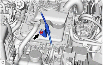
Remove the nut to separate the floor shift transmission control select cable.
17705
10.REMOVE AIR CLEANER CAP SUB-ASSEMBLY
11.REMOVE AIR CLEANER HOSE ASSEMBLY
53289A
12.REMOVE RADIATOR SUPPORT OPENING COVER
17752
13.REMOVE INLET NO. 2 AIR CLEANER
17801
14.REMOVE AIR CLEANER FILTER ELEMENT SUB-ASSEMBLY
17701
15.REMOVE AIR CLEANER CASE SUB-ASSEMBLY
17771A
16.REMOVE AIR CLEANER BRACKET
17751
17.REMOVE INLET NO. 1 AIR CLEANER
821H2
18.DISCONNECT HV AIR CONDITIONING WIRE
- CAUTION:
-
Be sure to wear insulated gloves.
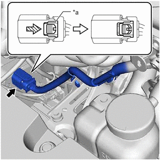
| *a | Green-colored Lock |

|
Slide |
Slide the green-colored lock of the connector as shown in the illustration to release it and disconnect the HV air conditioning wire.
- NOTICE:
-
Insulate the disconnected terminals with insulating tape.
82121
19.DISCONNECT ENGINE WIRE
- CAUTION:
-
Be sure to wear insulated gloves.
- NOTICE:
-
Do not allow any foreign matter or water to enter the inverter with converter assembly.
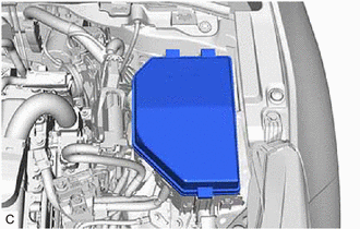
Remove the No. 1 relay block cover from the No. 1 engine room relay block.
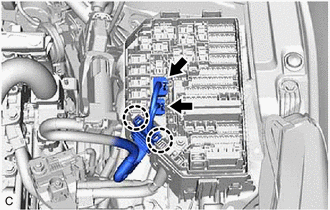
Disconnect the 2 No. 1 engine room relay block connectors.
Disengage the 2 claws to separate the engine wire from the No. 1 engine room relay block.
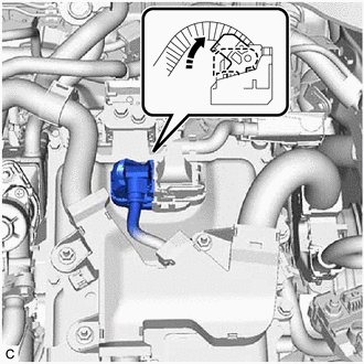
Move the lock lever as shown in the illustration and disconnect the inverter with converter assembly connector.
- NOTICE:
- ·
Do not touch the waterproof seal or terminals of the connector.
·Do not damage the terminals, connector housing or inverter with converter assembly during disconnection.
·Cover the hole where the cable was connected with tape (non-residue type) or equivalent to prevent entry of foreign matter.
·Insulate the disconnected terminals with insulating tape.
Remove the 3 nuts.
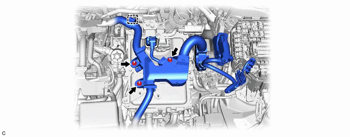
Disengage the clamp.
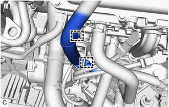
Disengage the 2 clamps and disconnect the engine wire from the inverter with converter assembly.
82111
20.DISCONNECT ENGINE ROOM MAIN WIRE
- CAUTION:
-
Be sure to wear insulated gloves.
- NOTICE:
-
Do not allow any foreign matter or water to enter the inverter with converter assembly.
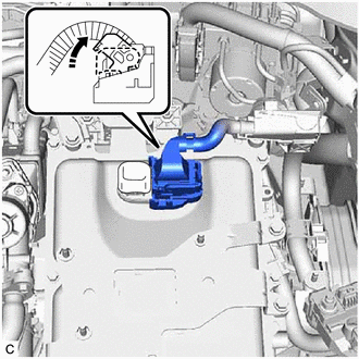
Move the lock lever as shown in the illustration and disconnect the inverter with converter assembly connector.
- NOTICE:
- ·
Do not touch the waterproof seal or terminals of the connector.
·Do not damage the terminals, connector housing or inverter with converter assembly during disconnection.
·Cover the hole where the cable was connected with tape (non-residue type) or equivalent to prevent entry of foreign matter.
·Insulate the disconnected terminals with insulating tape.
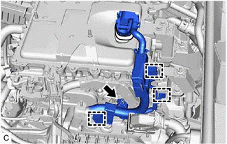
Disengage the 3 clamps.
Disconnect the connector and disconnect the engine room main wire from the inverter with converter assembly.
821H1
21.DISCONNECT FLOOR UNDER WIRE
- CAUTION:
-
Be sure to wear insulated gloves.
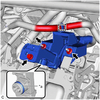
| *a | Waterproof Seal |
Disengage the clamp.
Remove the bolt, 2 nuts and disconnect the HV floor under wire from the inverter with converter assembly.
- NOTICE:
- ·
Do not touch the waterproof seal or terminals of the connector.
·Do not damage the terminals, connector housing or inverter with converter assembly during disconnection.
·Cover the hole where the cable was connected with tape (non-residue type) or equivalent to prevent entry of foreign matter.
·Do not allow any foreign matter or water to enter the inverter with converter assembly.
·Insulate the disconnected terminals with insulating tape.
82123
22.DISCONNECT NO. 3 ENGINE WIRE
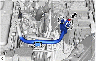
Remove the nut.
Disengage the 2 claws.
Disengage the clamp.
82127D
23.DISCONNECT NO. 7 ENGINE WIRE
- CAUTION:
-
Be sure to wear insulated gloves.
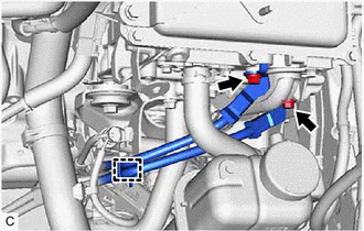
Remove the 2 bolts and disconnect the No. 3 engine wire from the inverter with converter assembly.
Disengage the clamp.
G922C
24.DISCONNECT OUTLET NO. 1 INVERTER COOLING HOSE
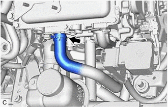
Slide the clip and disconnect the outlet No. 1 inverter cooling hose from the inverter with converter assembly.
- NOTICE:
-
Put pieces of cloth into the pipe and disconnected hose or cover the pipe and hose with plastic bags to prevent entry of foreign matter.
G922AA
25.DISCONNECT INLET NO. 1 INVERTER COOLING HOSE
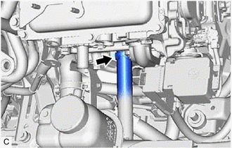
Slide the clip and disconnect the inlet No. 1 inverter cooling hose from the inverter with converter assembly.
- NOTICE:
-
Put pieces of cloth into the pipe and disconnected hose or cover the pipe and hose with plastic bags to prevent entry of foreign matter.
82121
26.DISCONNECT ENGINE WIRE
- CAUTION:
-
Be sure to wear insulated gloves.
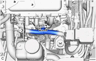
Disengage the clamp and disconnect the engine wire.
27.DISCONNECT INVERTER WITH CONVERTER ASSEMBLY
- CAUTION:
-
Be sure to wear insulated gloves.
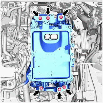
Remove the 4 bolts, 2 nuts to disconnect inverter with converter assembly.
- NOTICE:
-
To prevent damage due to static electricity, do not touch the terminals of the disconnected connectors.
G9221
28.REMOVE INVERTER COVER
- CAUTION:
-
Be sure to wear insulated gloves.
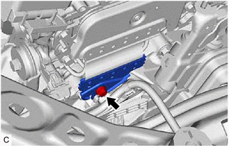
Remove the bolt and inverter cover from the hybrid vehicle transaxle assembly.
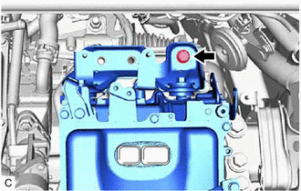
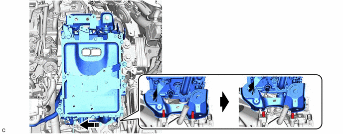
To prevent the inverter with converter assembly from falling, temporarily install the bolt in the location shown in the illustration.
Shift the position of the inverter with converter assembly and temporarily set it on top of the stud bolts as shown in the illustration.
- NOTICE:
-
When lifting, make sure not to apply force to the motor cable.
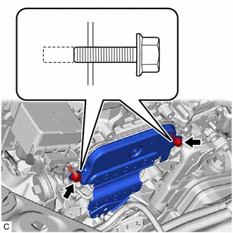
Loosen the 2 bolts, leaving 2 to 3 threads at the tip of the bolt still engaged.
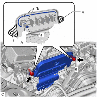
| *a | Interlock |
| *b | Waterproof Seal |
Using the 2 bolts as guides, remove the upper inverter cover from the inverter with converter assembly.
- NOTICE:
- ·
Make sure to pull the inverter cover straight out, as a connector is connected to the inside of the inverter cover.
·Do not touch the waterproof seal of the inverter cover.
·Do not allow any foreign matter or water to enter the inverter with converter assembly.
·When removing the inverter cover, do not pull the areas (A) as they may deform.
·Make sure that the interlock is installed to the inverter cover.
·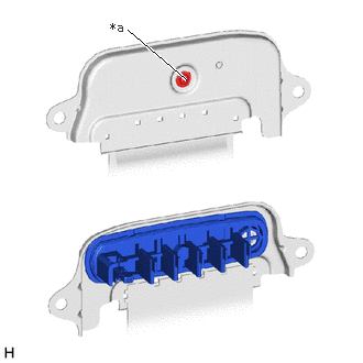 1.76,0.75 1.208,0.281 true 1.042,0.188 1.354,0.385 0.313,0.198 10 false *a
*a Screw
Do not remove or excessively tighten the screw of the inverter cover.
·Although the inverter cover may feel loose, this is not due to a malfunction.
·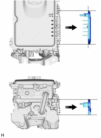
Hold the upper inverter cover horizontal while removing it.
- HINT:
-
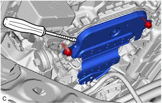
-
If necessary, use a screwdriver with its tip wrapped with protective tape as shown in the illustration to remove the inverter cover.
Remove the 2 bolts.
Shift the position of the inverter with converter assembly and temporarily set it on the hybrid vehicle transaxle assembly as shown in the illustration.
- NOTICE:
-
When lifting, make sure not to apply force to the motor cable.
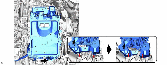
Remove the bolt.
G1148
29.DISCONNECT MOTOR CABLE
- CAUTION:
-
Be sure to wear insulated gloves.
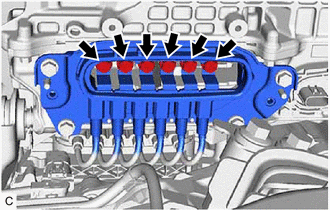
Remove the 6 bolts.
- CAUTION:
-
Insulate the tool with insulating tape.
- NOTICE:
-
Do not allow any foreign matter or water to enter the inverter with converter assembly.
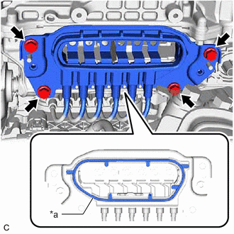
| *a | Waterproof Seal |
Remove the 4 bolts and disconnect the motor cable from the inverter with converter assembly.
- NOTICE:
- ·
Do not allow any foreign matter or water to enter the inverter with converter assembly.
·Do not touch the waterproof seal or terminals of the connector.
·Do not damage the terminals, connector housing or inverter with converter assembly during disconnection.
·Insulate the disconnected terminals with insulating tape.
·After disconnecting the motor cable, wrap it with a plastic bag or equivalent to protect it.
·Cover the hole where the cable was connected with tape (non-residue type) or equivalent to prevent entry of foreign matter.
·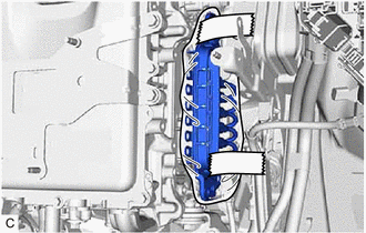
To prevent the wire harness from being caught, make sure to bundle the wire harness using insulating tape or equivalent.
30.REMOVE INVERTER WITH CONVERTER ASSEMBLY
- CAUTION:
-
Be sure to wear insulated gloves.
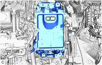
Remove the inverter with converter assembly.
- NOTICE:
- ·
When removing the inverter with converter assembly, be careful not to damage the parts around it.
·To prevent damage, do not hold the inverter with converter assembly by the connectors, brackets or cooling pipes.
·To prevent damage due to static electricity, do not touch the terminals of the disconnected connectors.
- HINT:
-
Even after the coolant is drained, coolant remains in the inverter due to its internal structure. Therefore, seal or cover the pipes when removing the inverter with converter assembly so that coolant does not spill out.