8ZR-FXE INTAKE / EXHAUST EXHAUST PIPE INSTALLATION
PROCEDURE

 17410
1.INSTALL FRONT EXHAUST PIPE ASSEMBLY
17410
1.INSTALL FRONT EXHAUST PIPE ASSEMBLY
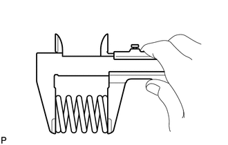
Using a vernier caliper, measure the free length of the compression springs.
| Minimum Free Length | 41.5 mm (1.63 in.) |
If the free length is less than the minimum, replace the compression spring.
Temporarily install a new gasket to the exhaust manifold.
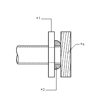
| *1 | Exhaust Manifold |
| *2 | Gasket |
| *a | Wooden Block |
Using a plastic hammer and wooden block, tap in the gasket until its surface is flush with the exhaust manifold.
- NOTICE:
- ·
Be careful with the installation direction of the gasket.
·Do not reuse the gasket.
·Do not damage the gasket.
·Do not push in the gasket by using the exhaust pipes when connecting them.
Connect the front exhaust pipe assembly to the 2 exhaust pipe supports.
Install the front exhaust pipe assembly to the exhaust manifold with the 2 compression springs and 2 bolts.
- Torque:
- 43 N*m (438 kgf*cm, 32 ft.*lbf)
- HINT:
-
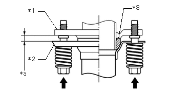 2.406,0.771 2.51,0.167 2.51,0.167 2.677,0.167 false 0.771,0.229 0.906,0.229 0.906,0.229 1.156,0.594 false 0.771,1.198 0.927,1.198 0.927,1.198 1.094,0.896 false 0.406,1.417 0.615,1.573 0.208,0.156 10 *a 0.573,0.146 0.823,0.302 0.25,0.156 10 *1 0.573,1.125 0.813,1.313 0.24,0.188 10 *2 2.698,0.083 2.927,0.26 0.229,0.177 10 *3
*1 Exhaust Manifold *2 Front Exhaust Pipe Assembly *3 Gasket *a Space between Flanges: 8.5 mm (0.335 in.)
-
After installation, check that the space between the flanges of the exhaust manifold and front exhaust pipe assembly is consistent front-to-rear and left-to-right.
Engage the wire harness clamp.
Connect the heated oxygen sensor connector.
89425
2.INSTALL NO. 1 EXHAUST GAS TEMPERATURE SENSOR
89465
3.INSTALL HEATED OXYGEN SENSOR
17430
4.INSTALL TAIL EXHAUST PIPE ASSEMBLY
Using a vernier caliper, measure the free length of the compression springs.
| Minimum Free Length | 38.5 mm (1.52 in.) |
If the free length is less than the minimum, replace the compression spring.
Temporarily install a new gasket to the front exhaust pipe assembly.
| *1 | Front Exhaust Pipe Assembly |
| *2 | Gasket |
| *a | Wooden Block |
Using a plastic hammer and wooden block, tap in the gasket until its surface is flush with the front exhaust pipe assembly.
- NOTICE:
- ·
Be careful with the installation direction of the gasket.
·Do not reuse the gasket.
·Do not damage the gasket.
·Do not push in the gasket by using the exhaust pipes when connecting them.
Connect the tail exhaust pipe assembly to the 4 exhaust pipe supports.
Install the tail exhaust pipe assembly to the front exhaust pipe assembly with the 2 bolts and 2 compression springs.
- Torque:
- 43 N*m (438 kgf*cm, 32 ft.*lbf)
- HINT:
-
2.406,0.771 2.51,0.167 2.51,0.167 2.677,0.167 false 0.771,0.229 0.906,0.229 0.906,0.229 1.156,0.594 false 0.771,1.198 0.927,1.198 0.927,1.198 1.094,0.896 false 0.406,1.417 0.615,1.573 0.208,0.156 10 *a 0.573,0.146 0.823,0.302 0.25,0.156 10 *1 0.573,1.125 0.813,1.313 0.24,0.188 10 *2 2.698,0.083 2.927,0.26 0.229,0.177 10 *3
*1 Front Exhaust Pipe Assembly *2 Tail Exhaust Pipe Assembly *3 Gasket *a Space between Flanges: 6.5 mm (0.256 in.)
-
After installation, check that the space between the flanges of the tail exhaust pipe assembly and front exhaust pipe assembly is consistent front-to-rear and left-to-right.
57533B
5.INSTALL FRONT FLOOR CENTER BRACE
58166A
6.INSTALL FRONT FLOOR COVER LH
58165C
7.INSTALL FRONT FLOOR COVER RH
- HINT:
-
Perform the same procedure as for the front floor cover LH.
8.INSPECT FOR EXHAUST GAS LEAK
If gas is leaking, tighten the areas necessary to stop the leak. Replace damaged parts as necessary.
Perform "Inspection After Repair" after repairing an exhaust gas leak.
9. GPF DEPOSITION VALUE CLEAR
- HINT:
-
It requires when replacing the front exhaust pipe assembly.