WINDOW / GLASS WINDOW DEFOGGER SYSTEM Rear Window Defogger System does not Operate
DESCRIPTION
When the window defogger switch on the center cluster module control assembly (window defogger switch) is pressed, the operation signal is transmitted to the air conditioning amplifier assembly via LIN communication. When the air conditioning amplifier assembly receives the signal, it turns on the defogger relay (DEF) to operate the window defogger system.
WIRING DIAGRAM
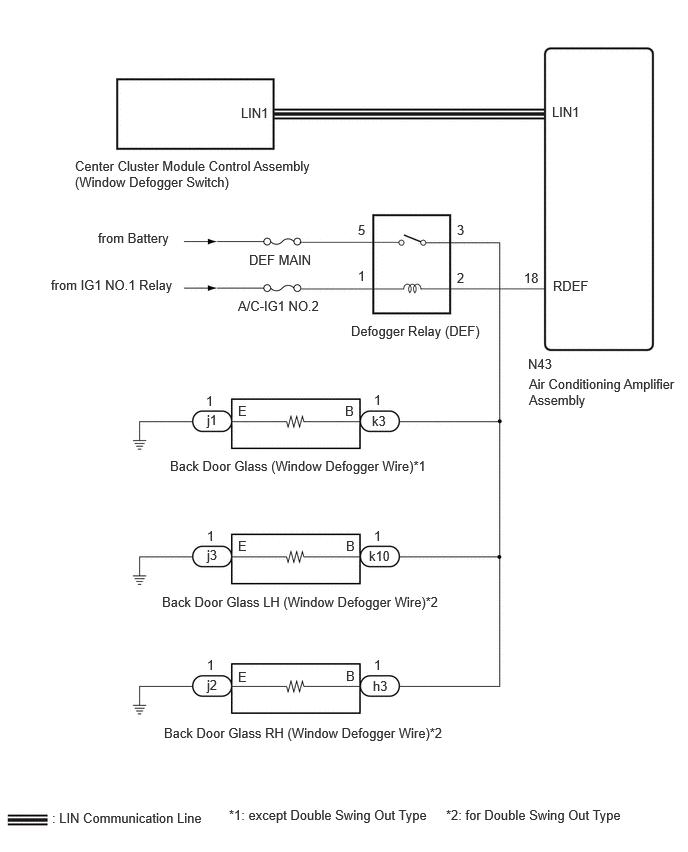
CAUTION / NOTICE / HINT
- NOTICE:
-
Inspect the fuses for circuits related to this system before performing the following procedure.
PROCEDURE
Check the air conditioning system.
- HINT:
-
Both the window defogger system operation signal and air conditioning system operation signal are transmitted to the air conditioning amplifier assembly via the same communication line.
- OK:
The air conditioning system operates normally.
- Result:
Proceed to OK NG
OK
NG
Check that the indicator light illuminates when the window defogger switch is on.
- OK:
Indicator light illuminates.
- Result:
Proceed to OK NG
OK
NG
Using the GTS, perform the Active Test.
- Body Electrical > Air Conditioner > Active Test
-
Tester Display Measurement Item Control Range Diagnostic Note Defogger Relay (Rear) Defogger relay (DEF) OFF or ON -
- Body Electrical > Air Conditioner > Active Test
-
Tester Display Defogger Relay (Rear) - 50004 121 22
- OK:
Back door glass (defogger wire) warms up.
- Result:
Proceed to OK NG
OK
NG
Replace the air conditioning amplifier assembly.
Check that the window defogger system operates normally.
- OK:
The window defogger system operates normally.
- Result:
Proceed to OK NG
OK
NG
Check the vehicle type.
- Result:
Result Proceed to except Double Swing Out Type A for Double Swing Out Type B
A
B
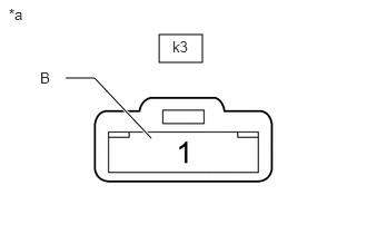
| *a | Front view of wire harness connector
(to Back Door Glass [Defogger Wire]) |
Disconnect the back door glass (defogger wire) connector.
Measure the voltage according to the value(s) in the table below.
- Standard Voltage:
Tester Connection Switch Condition Specified Condition k3-1 (B) - Body ground Ignition switch ON, window defogger switch on 11 to 14 V Ignition switch ON, window defogger switch off Below 1 V
- Result:
Proceed to OK NG
OK
NG
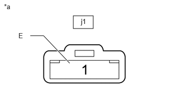
| *a | Front view of wire harness connector
(to Back Door Glass [Defogger Wire]) |
Disconnect the back door glass (defogger wire) connector.
Measure the resistance according to the value(s) in the table below.
- Standard Resistance:
Tester Connection Condition Specified Condition j1-1 (E) - Body ground Always Below 1 Ω
- Result:
Proceed to OK NG
OK
NG
Remove the defogger relay (DEF) from the No. 1 engine room relay block.
Inspect the defogger relay (DEF).
- Result:
Proceed to OK NG
OK
NG
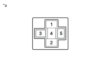
| *a | Front view of wire harness connector
(to Defogger Relay [DEF]) |
Remove the defogger relay (DEF) from the No. 1 engine room relay block.
Measure the voltage according to the value(s) in the table below.
- Standard Voltage:
Tester Connection Condition Specified Condition Defogger relay (DEF) terminal 1 - Body ground Ignition switch ON 11 to 14 V Defogger relay (DEF) terminal 5 - Body ground Always 11 to 14 V
- Result:
Proceed to OK NG
OK
NG
Remove the defogger relay (DEF) from the No. 1 engine room relay block.
Disconnect the N43 air conditioning amplifier assembly connector.
Disconnect the k3 back door glass (defogger wire) connector.
Measure the resistance according to the value(s) in the table below.
- Standard Resistance:
Tester Connection Condition Specified Condition Defogger relay (DEF) terminal 2 - N43-18 (RDEF) Always Below 1 Ω Defogger relay (DEF) terminal 3 - k3-1 (B) Always Below 1 Ω Defogger relay (DEF) terminal 2 or N43-18 (RDEF) - Body ground Always 10 kΩ or higher Defogger relay (DEF) terminal 3 or k3-1 (B) - Body ground Always 10 kΩ or higher
- Result:
Proceed to OK NG
OK
NG
Check the vehicle condition.
- Result:
Result Proceed to Back door glass LH (defogger wire) does not warms up. A Back door glass RH (defogger wire) does not warms up. B Both back door glass LH (defogger wire) and back door glass RH (defogger wire) do not warms up. C
A
B
C
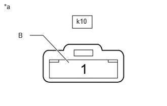
| *a | Front view of wire harness connector
(to Back Door Glass LH [Defogger Wire]) |
Disconnect the back door glass LH (defogger wire) connector.
Measure the voltage according to the value(s) in the table below.
- Standard Voltage:
Tester Connection Switch Condition Specified Condition k10-1 (B) - Body ground Ignition switch ON, window defogger switch on 11 to 14 V Ignition switch ON, window defogger switch off Below 1 V
- Result:
Proceed to OK NG
OK
NG
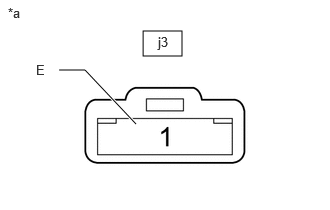
| *a | Front view of wire harness connector
(to Back Door Glass [Defogger Wire]) |
Disconnect the back door glass LH (defogger wire) connector.
Measure the resistance according to the value(s) in the table below.
- Standard Resistance:
Tester Connection Condition Specified Condition j3-1 (E) - Body ground Always Below 1 Ω
- Result:
Proceed to OK NG
OK
NG
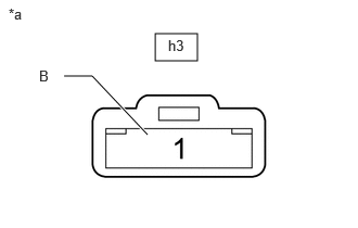
| *a | Front view of wire harness connector
(to Back Door Glass RH [Defogger Wire]) |
Disconnect the back door glass RH (defogger wire) connector.
Measure the voltage according to the value(s) in the table below.
- Standard Voltage:
Tester Connection Switch Condition Specified Condition h3-1 (B) - Body ground Ignition switch ON, window defogger switch on 11 to 14 V Ignition switch ON, window defogger switch off Below 1 V
- Result:
Proceed to OK NG
OK
NG
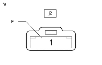
| *a | Front view of wire harness connector
(to Back Door Glass [Defogger Wire]) |
Disconnect the back door glass RH (defogger wire) connector.
Measure the resistance according to the value(s) in the table below.
- Standard Resistance:
Tester Connection Condition Specified Condition j2-1 (E) - Body ground Always Below 1 Ω
- Result:
Proceed to OK NG
OK
NG
Remove the defogger relay (DEF) from the No. 1 engine room relay block.
Inspect the defogger relay (DEF).
- Result:
Proceed to OK NG
OK
NG
| *a | Front view of wire harness connector
(to Defogger Relay [DEF]) |
Remove the defogger relay (DEF) from the No. 1 engine room relay block.
Measure the voltage according to the value(s) in the table below.
- Standard Voltage:
Tester Connection Condition Specified Condition Defogger relay (DEF) terminal 1 - Body ground Ignition switch ON 11 to 14 V Defogger relay (DEF) terminal 5 - Body ground Always 11 to 14 V
- Result:
Proceed to OK NG
OK
NG
Remove the defogger relay (DEF) from the No. 1 engine room relay block.
Disconnect the N43 air conditioning amplifier assembly connector.
Disconnect the k10 back door glass LH (defogger wire) connector.
Measure the resistance according to the value(s) in the table below.
- Standard Resistance:
Tester Connection Condition Specified Condition Defogger relay (DEF) terminal 2 - N43-18 (RDEF) Always Below 1 Ω Defogger relay (DEF) terminal 3 - k10-1 (B) Always Below 1 Ω Defogger relay (DEF) terminal 2 or N43-18 (RDEF) - Body ground Always 10 kΩ or higher Defogger relay (DEF) terminal 3 or k10-1 (B) - Body ground Always 10 kΩ or higher
- Result:
Proceed to OK NG
OK
NG