DOOR / HATCH BACK DOOR(for Double Swing Out Type) ADJUSTMENT
CAUTION / NOTICE / HINT
- HINT:
-
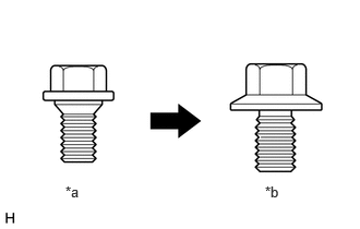 0.625,1.75 0.823,1.938 0.198,0.188 10 false *a 2.531,1.75 2.729,1.938 0.198,0.188 10 false *b
*a Centering Bolt *b Standard Bolt
-
Centering bolts are used to mount the door hinge to the vehicle body and door. The door cannot be adjusted with the centering bolts on. Substitute the centering bolts for standard bolts when making adjustments.
PROCEDURE

 67005
1.INSPECT BACK DOOR PANEL SUB-ASSEMBLY
67005
1.INSPECT BACK DOOR PANEL SUB-ASSEMBLY
for Standard Roof:
Check that the clearance measurements of areas A to K are within the standard ranges.
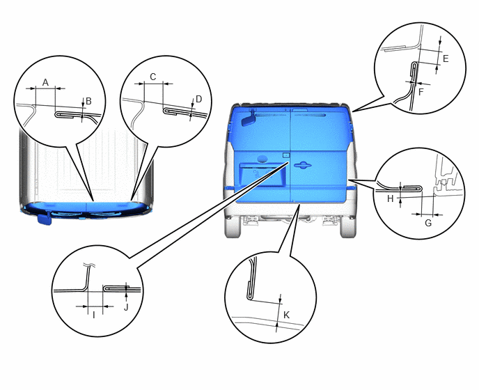
- Standard Clearance:
Area Measurement Area Measurement A 7.1 to 11.1 mm (0.280 to 0.437 in.) B 0.5 to 4.5 mm (0.0197 to 0.1772 in.) C 7.1 to 11.1 mm (0.280 to 0.437 in.) D -0.4 to 3.6 mm (-0.0157 to 0.1417 in.) E 4.1 to 7.1 mm (0.161 to 0.280 in.) F -1.5 to 1.5 mm (-0.0591 to 0.0591 in.) G
(Reference)3.35 to 7.35 mm (0.132 to 0.289 in.) H
(Reference)0.45 to 4.45 mm (0.0177 to 0.1752 in.) I 3.2 to 8.2 mm (0.126 to 0.323 in.) J -2.0 to 2.0 mm (-0.0787 to 0.0787 in.) K 4.95 to 10.95 mm (0.195 to 0.431 in.) - -
for High Roof:
Check that the clearance measurements of areas A to K are within the standard ranges.
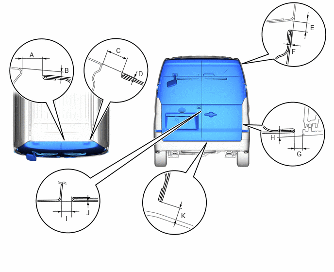
- Standard Clearance:
Area Measurement Area Measurement A 12.3 to 16.3 mm (0.484 to 0.642 in.) B 1.3 to 5.3 mm (0.0512 to 0.2087 in.) C 12.4 to 16.4 mm (0.488 to 0.646 in.) D -1.6 to 2.4 mm (-0.0630 to 0.0945 in.) E 4.7 to 7.7 mm (0.185 to 0.303 in.) F -1.5 to 1.5 mm (-0.0591 to 0.0591 in.) G
(Reference)3.35 to 7.35 mm (0.132 to 0.289 in.) H
(Reference)0.45 to 4.45 mm (0.0177 to 0.1752 in.) I 3.2 to 8.2 mm (0.126 to 0.323 in.) J -2.0 to 2.0 mm (-0.0787 to 0.0787 in.) K 4.95 to 10.95 mm (0.195 to 0.431 in.) - -
67935
2.REMOVE BACK DOOR SCUFF PLATE
69455A
3.REMOVE BACK DOOR UPPER LOCK STRIKER COVER
4.REMOVE REAR COMBINATION LIGHT ASSEMBLY LH
5.REMOVE REAR COMBINATION LIGHT ASSEMBLY RH
- HINT:
-
Use the same procedure described for the LH side.
67005
6.ADJUST BACK DOOR PANEL SUB-ASSEMBLY
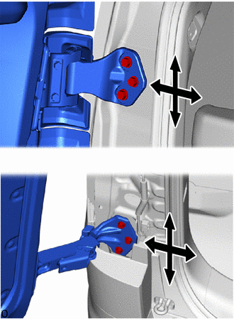
Loosen the hinge bolts on the body and adjust the door position.
Tighten the hinge bolts on the body after the adjustment.
- Torque:
- 28 N*m (286 kgf*cm, 21 ft.*lbf)
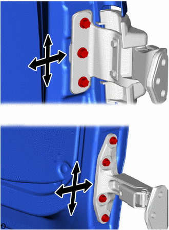
Loosen the hinge bolts on the door and adjust the door position.
Tighten the hinge bolts on the door after the adjustment.
- Torque:
- 31 N*m (316 kgf*cm, 23 ft.*lbf)
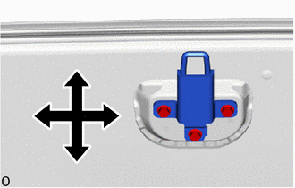
Adjust the striker position by slightly loosening the striker mounting bolts and hitting the striker with a plastic-faced hammer.
Tighten the striker mounting bolts after the adjustment.
- Torque:
- 19 N*m (194 kgf*cm, 14 ft.*lbf)
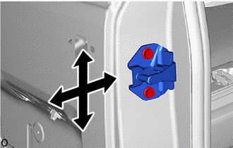
Adjust the striker position by slightly loosening the striker mounting bolts and hitting the striker with a brass bar and a hammer.
Tighten the striker mounting bolts after the adjustment.
- Torque:
- 19 N*m (194 kgf*cm, 14 ft.*lbf)
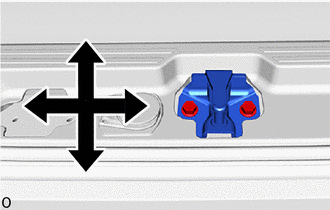
Adjust the striker position by slightly loosening the striker mounting bolts and hitting the striker with a brass bar and a hammer.
Tighten the striker mounting bolts after the adjustment.
- Torque:
- 19 N*m (194 kgf*cm, 14 ft.*lbf)
7.INSTALL REAR COMBINATION LIGHT ASSEMBLY LH
8.INSTALL REAR COMBINATION LIGHT ASSEMBLY RH
- HINT:
-
Use the same procedure described for the LH side.
69455A
9.INSTALL BACK DOOR UPPER LOCK STRIKER COVER
67935
10.INSTALL BACK DOOR SCUFF PLATE