CRUISE CONTROL MILLIMETER WAVE RADAR SENSOR ADJUSTMENT
PROCEDURE

 1. PREPARATION FOR MILLIMETER WAVE RADAR SENSOR ASSEMBLY ADJUSTMENT
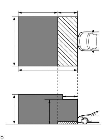
| *a | 5 m (16.4 ft.) |
| *b | 6 m (19.7 ft.) |
| *c | 4 m (13.1 ft.) |
| *d | 2 m (6.56 ft.) |
| *e | 3 m (9.84 ft.) |
| *f | 1.5 m (4.92 ft.) |
| *g | 2.5 m (8.2 ft.) |

|
Do not place any metal objects in this area |

|
Do not place metal objects with a height of more than 50 mm (1.97 in.) in this area |
Park the vehicle on a level surface where the area in front of the vehicle shown in the illustration is free of metal objects.
- HINT:
-
Metal objects that have a height of 50 mm (1.97 in.) or less do not affect adjustment within 2 m (6.56 ft.) from the front of the vehicle.
Check the levelness of the ground.
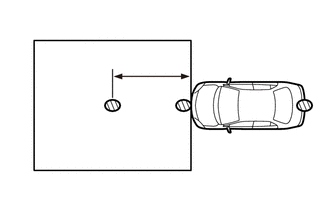
| *a | 3 m (9.84 ft.) |
|
|
Levelness Check Point |
Check the levelness of the ground at the 3 points shown in the illustration.
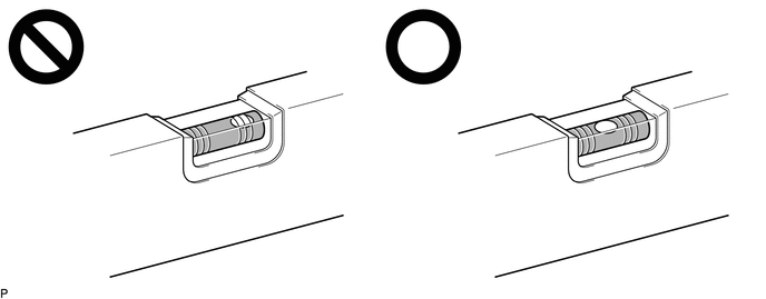
Place the level on each levelness check point and check that the air bubble of the level is centered.
Adjust the tire inflation pressure to the specified pressure.
Clean the radiator grille sub-assembly or millimeter wave radar sensor assembly.
Visually inspect the front of the vehicle.
- HINT:
-
Confirm that there is no damage or deformation.
Visually inspect the front bumper assembly, radiator grille and stays.
- HINT:
-
Confirm that there is no damage or deformation.
2. MILLIMETER WAVE RADAR SENSOR ASSEMBLY VERTICALLY AND HORIZONTALLY
| *a | SST (reflector) |
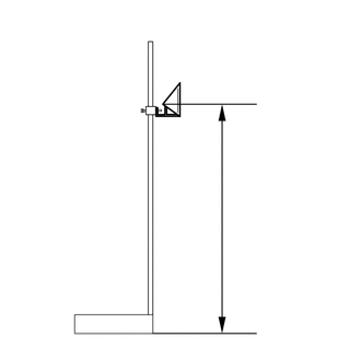
Adjust SST (reflector) height.
Adjust SST (reflector) so that the center of SST (reflector) is the same height as the millimeter wave radar sensor.
- HINT:
-
Make sure to align the center of SST (reflector) with the millimeter wave radar sensor (the center of the emblem).
- Reference Value:
About 833 mm (2.73 ft.)
- SST
- 09870-60000 (09870-60010)
09870-60040
Place SST (reflector).
except Double Swing Out Type:
Hang a weight with a pointed tip from the No. 2 back door name plate, and mark the rear center point of the vehicle (point A) on the ground.

| *a | String | *b | Weight |
| *c | Center | *d | Bilateral Symmetry |
- HINT:
-
Lightly flick the string with your fingers several times to confirm that the string is perpendicular to the ground.
for Double Swing Out Type:
Hang a weight with a pointed tip from the center of the back door panel end face, and mark the rear center point of the vehicle (point A) on the ground.
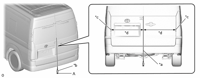
| *a | String | *b | Weight |
| *c | Back Door Panel End Face | *d | Bilateral Symmetry |
- HINT:
-
Lightly flick the string with your fingers several times to confirm that the string is perpendicular to the ground.
Hang a weight with a pointed tip from the center of the radiator grille (or front panel) emblem, and mark the front center point of the vehicle (point B) on the ground (placement position).
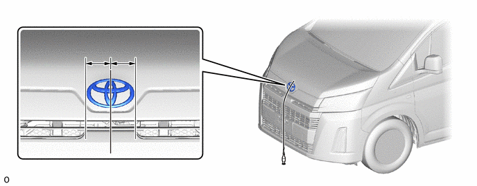
| *a | String | *b | Weight |
| *c | Center | *d | Bilateral Symmetry |
- HINT:
-
Lightly flick the string with your fingers several times to confirm that the string is perpendicular to the ground.
Using tape and a string, create a line that connects point B to point A and extends at least 3000 mm (9.84 ft.) beyond the front center point of the vehicle.
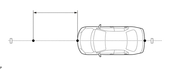
| *a | String | *b | Tape |
| *c | 3000 mm (9.84 ft.) | - | - |
- HINT:
- ·
Make sure the string is taut when securing it with tape.
·Lightly flick the string with your fingers several times to confirm that the string is aligned with point B.
Mark point C (SST (reflector) placement position) at a position 3000 mm (9.84 ft.) from point B.
Place SST (reflector) at point C.
Front Beam Axis Adjustment:
- NOTICE:
- ·
Close all of the doors.
·Ensure that nobody enters the adjustment area during the adjustment.
·Do not move or shake the vehicle during adjustment (do not get in or out of the vehicle).
·Do not turn off the GTS or ignition switch.
·If the vehicle moves or is shaken during beam axis adjustment such as during strong winds or a door is opened or closed, perform the adjustment again.
Connect the GTS to the DLC3.
Turn the ignition switch to ON.
Turn the GTS on.
Enter the following menus: Body Electrical / Front Radar Sensor / Utility / Front Beam Axis Adjustment.
- Body Electrical > Front Radar Sensor > Utility
-
Tester Display Front Beam Axis Adjustment - 50005 429 4404
Press "Next".
Perform the adjustment according to the display on the GTS.
- NOTICE:
-
If an error code is displayed, perform troubleshooting according to the following table, then perform the adjustment again.
| Error No. | Error Description | Cause of Error | Action to be Taken |
|---|---|---|---|
| 1 | No target abnormality | ·
SST (reflector) is placed incorrectly. ·
The radiator grille garnish or millimeter wave radar sensor assembly is covered by dirt or snow. |
Place SST (reflector) in the correct position. (See page 2. MILLIMETER WAVE RADAR SENSOR ASSEMBLY VERTICALLY AND HORIZONTALLY (b) Place SST (reflector)) |
| Clean the radiator grille garnish or millimeter wave radar sensor assembly. | |||
| 2 | Target distance abnormality | ·
SST (reflector) is placed incorrectly. |
Place SST (reflector) in the correct position. (See page 2. MILLIMETER WAVE RADAR SENSOR ASSEMBLY VERTICALLY AND HORIZONTALLY (b) Place SST (reflector)) |
| 3 | Plural targets abnormality | ·
There is a reflective object near SST (reflector). ·
A person entered the adjustment area. |
Remove any reflective objects. |
| Ensure that nobody enters the adjustment area during the adjustment. (See page 1. PREPARATION FOR MILLIMETER WAVE RADAR SENSOR ASSEMBLY ADJUSTMENT) | |||
| 4 | Target move abnormality | ·
SST (reflector) was moved out of position or shaking during the adjustment due to wind. ·
A person entered the adjustment area. |
Place SST (reflector) in the correct position. (See page 2. MILLIMETER WAVE RADAR SENSOR ASSEMBLY VERTICALLY AND HORIZONTALLY (b)Place SST (reflector)) |
| Perform adjustment in an area with no wind. | |||
| Ensure that nobody enters the adjustment area during the adjustment. (See page 1. PREPARATION FOR MILLIMETER WAVE RADAR SENSOR ASSEMBLY ADJUSTMENT) | |||
| 5 | Axis adjustment | ·
Optical axis adjustment has not been performed. |
Optical axis adjustment. (See page 2. MILLIMETER WAVE RADAR SENSOR ASSEMBLY VERTICALLY AND HORIZONTALLY (c) Front Beam Axis Adjustment) |
| 6 | Target angle abnormality | ·
SST (reflector) is placed incorrectly. ·
The beam axis of the millimeter wave radar sensor assembly is outside the automatic correction range. |
Place SST (reflector) in the correct position. (See page 2. MILLIMETER WAVE RADAR SENSOR ASSEMBLY VERTICALLY AND HORIZONTALLY (b)Place SST (reflector)) |
| Check the condition of the millimeter wave radar sensor assembly. | |||
| Check the condition of the radiator grille and front bumper assembly. | |||
| 7 | Radar abnormality | ·
Operation of the millimeter wave radar sensor assembly is abnormal. |
Replace the millimeter wave radar sensor assembly. |
| 8 | Radar dirtiness | ·
There is dirt on the radiator grille garnish or millimeter wave radar sensor assembly. |
Clean the radiator grille garnish or millimeter wave radar sensor assembly. |
| 9 | Temperature abnormality | ·
The temperature around the millimeter wave radar sensor assembly is too high. |
Wait until the temperature drops to the operable range (-30 to 50°C). |
| 10 | Voltage abnormality | ·
IG power source voltage is outside the operable range of the millimeter wave radar sensor assembly. |
Check the battery voltage (specified condition: 10 to 16 V).
for 7GR-FKS:(  201902,999999,_57,_078664,_0387111,RM100000001GV5J_01_0012,) 201902,999999,_57,_078664,_0387111,RM100000001GV5J_01_0012,)
for 1GD-FTV:( 201902,999999,_57,_078663,_0383346,RM100000001GV2F_01_0012,)
|
| 11 | External communication abnormality | ·
CAN communication between forward recognition camera and the millimeter wave radar sensor assembly is abnormal. |
Check the condition of the connectors and wire harness. |
| 12 | Radar axis aiming failure upward | ·
The beam axis of the millimeter wave radar sensor assembly is outside the automatic correction range (upward). ·
Road inclement is outside the standard value. |
Check the condition of the millimeter wave radar sensor assembly. |
| Confirm road gradient. | |||
| 13 | Radar axis aiming failure downward | ·
The beam axis of the millimeter wave radar sensor assembly is outside the automatic correction range (downward). ·
Road inclement is outside the standard value. |
Check the condition of the millimeter wave radar sensor assembly. |
| Confirm road gradient. | |||
| 14 | Vehicle speed abnormality | ·
The vehicle is not stationary. |
Ensure that the vehicle remains stationary. |
| 15 | Other | ·
A mode change error occurred. ·
Operation of the yaw rate sensor is abnormal. ·
The vehicle is shaking. |
Check for DTCs.
( 201902,999999,_51,_078884,_0383149,RM100000001G9IB,)
|
| Check for DTCs.
w/ VSC OFF Switch:( 201902,999999,_54,_078667,_0385049,RM100000001GK1S,)
w/o VSC OFF Switch:( 201902,999999,_54,_078667,_0383093,RM100000001G8WY,)
|
|||
| Ensure that the vehicle remains stationary. | |||
| 16 | Time out | ·
The vehicle cannot communicate with GTS normally. ·
The vehicle does not keep still during beam axis adjustment. ·
Operation of the millimeter wave radar sensor assembly is abnormal. |
·
Ensure that the vehicle is connected with the GTS correctly. ·
Ensure that the vehicle remains stationary. ·
Replace the millimeter wave radar sensor assembly. |
| 17 | Target parameter abnormality | ·
Wrong mode is selected. |
Perform beam axis adjustment again. |
| 18 | Vehicle information undefined | ·
CAN communication between forward recognition camera and the millimeter wave radar sensor assembly is abnormal. |
Check the condition of the connectors. |
Press "Exit" to finish front beam axis adjustment.
Front Beam Axis Misalignment Reading:
- NOTICE:
- ·
Close all of the doors.
·Ensure that nobody enters the adjustment area during the adjustment.
·Do not move or shake the vehicle during adjustment (do not get in or out of the vehicle).
·Do not turn off the GTS or ignition switch.
·If the vehicle moves or is shaken during beam axis adjustment such as during strong winds or a door is opened or closed, perform the adjustment again.
Enter the following menus: Body Electrical / Front Radar Sensor / Utility / Front Beam Axis Misalignment Reading.
- Body Electrical > Front Radar Sensor > Utility
-
Tester Display Front Beam Axis Misalignment Reading - 50005 429 4405
Press "Next".
Perform the adjustment according to the display on the GTS.
- Specified Condition:
Vertical -0.5 to 0.5 deg. Horizontal -0.5 to 0.5 deg.
- NOTICE:
-
If the result is not as specified, perform beam axis adjustment again.
Front Radar Acceleration Sensor Calibration:
Enter the following menus: Body Electrical / Front Radar Sensor / Utility / Front Radar Acceleration Sensor Calibration.
- Body Electrical > Front Radar Sensor > Utility
-
Tester Display Front Radar Acceleration Sensor Calibration - 50005 429 4506
Turn the ignition switch off.
Disconnect the GTS from the DLC3.
After beam axis adjustment completes, clear the following system vehicle control history entries.
Clear vehicle control history (Dynamic radar cruise control system).
Clear vehicle control history (Lane control system).
Clear vehicle control history (Road sign assist system).
Clear vehicle control history (Front radar sensor system).
Clear vehicle control history (Pre-collision system).
Clear vehicle control history (Lighting system (w/o Headlight ECU)).
Clear vehicle control history (Lighting system (w/ Headlight ECU)).