7GR-FKS ENGINE MECHANICAL CYLINDER BLOCK DISASSEMBLY
CAUTION / NOTICE / HINT
The necessary procedures (adjustment, calibration, initialization, or registration) that must be performed after parts are removed, installed, or replaced during the cylinder block sub-assembly disassembly/reassembly are shown below.
| Replaced Part or Performed Procedure | Necessary Procedure | Effect/Inoperative Function when Necessary Procedure not Performed | Link |
|---|---|---|---|
| Battery terminal is disconnected/reconnected | Memorize steering angle neutral point | Parking assist monitor system | ( 201902,999999,_56,_079315,_0385736,RM100000001GNRA,) 201902,999999,_56,_079315,_0385736,RM100000001GNRA,)
|
| Panoramic view monitor system | (201906,999999,_56,_079315,_0396274,RM100000001IGR3,)
|
||
| Replacement of ECM | Perform Vehicle Identification Number (VIN) or frame number registration | DTC P063051 is stored | (201902,999999,_51,_078720,_0381907,RM100000001G2WM,)
|
| ECU communication ID registration | Engine start function | See Service Bulletin for the registration method. | |
for RC60J:
Performing iMT installation information reset |
·
iMT system ·
DTCs are output |
(201902,999999,_52,_078740,_0383349,RM100000001GAF2,)
|
|
·
Throttle body with motor assembly ·
Cleaning the deposits from the throttle body with motor assembly ·
Engine assembly ·
Cylinder head sub-assembly ·
Camshaft (for intake or exhaust camshaft) ·
Camshaft timing gear assembly ·
Camshaft timing exhaust gear assembly ·
Piston or piston ring ·
Fuel injector assembly (for port injection) ·
Fuel injector assembly (for direct injection) ·
Fuel pump assembly (for high pressure side) ·
Engine coolant temperature sensor ·
Spark plug ·
Ignition coil assembly ·
Air leaks from intake system ·
Gas leaks from exhaust system |
Inspection after repair | ·
Poor idle, etc. ·
Engine start function, etc. |
(201902,999999,_51,_078720,_0381907,RM100000001G2VV,)
|
for AC60E:
Replacement of automatic transmission assembly |
Reset memory | ·
Large shift shock ·
Engine overruns |
(201902,999999,_52,_078741,_0385245,RM100000001GL7C,)
|
for AC60E:
Replacement of automatic transmission fluid |
ATF thermal degradation estimate reset | The value of the Data List item "ATF Thermal Degradation Estimate" is not estimated correctly | |
| Front wheel alignment adjustment | ·
Perform reset memory ·
Perform acceleration sensor zero point calibration and store system information memorization. |
·
VSC is disabled or malfunctions ·
DTCs are output ·
Slip indicator light illuminates ·
ABS warning light illuminates |
(201902,999999,_54,_078667,_0385049,RM100000001GK1P,)
|
| Suspension, tires, etc. | Television camera assembly optical axis (Back camera position setting) | Parking assist monitor system | (201902,999999,_56,_079315,_0385736,RM100000001GNRB,)
|
- HINT:
-
When the cable is disconnected / reconnected to the battery terminal, systems temporarily stop operating. However, each system has a function that completes learning the first time the system is used.
- ·
Learning completes when vehicle is driven
Effect/Inoperative when not Performed Necessary Procedures Link Lane control system Drive the vehicle straight ahead at 15 km/h (10 mph) or more for 1 second or more. ( 201902,999999,_58,_078886,_0382740,RM100000001G6XB,)
Pre-collision system
·Learning completes when vehicle is operated normally
Effect/Inoperative when not Performed Necessary Procedures Link Power slide door system Fully close the slide door by hand.
- HINT:
-
Initialization is not necessary if the above procedures are performed while the slide door is closed.
( 201902,999999,_59,_078503,_0381017,RM100000001FWXM,)
Air conditioning system After the ignition switch is turned to ON, the servo motor standard position is recognized. -
- CAUTION:
- ·
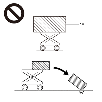 2.219,0.813 2.646,0.813 false 2.698,0.729 3.01,0.927 0.313,0.198 10 false *a
*a An Object Exceeding Weight Limit of Engine Lifter
The engine assembly with transmission is very heavy. Be sure to follow the procedure described in the repair manual, or the engine lifter may suddenly drop or the engine assembly may fall off the engine lifter.
·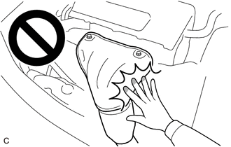
To prevent burns, do not touch the engine, exhaust manifold or other high temperature components while the engine is hot.
PROCEDURE

 1.INSPECT CONNECTING ROD THRUST CLEARANCE
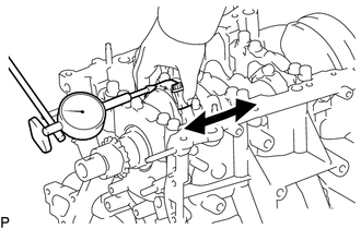
Using a dial indicator, measure the thrust clearance while moving the connecting rod back and forth.
- Standard thrust clearance:
0.15 to 0.40 mm (0.00591 to 0.0157 in.)
- Maximum thrust clearance:
0.50 mm (0.0197 in.)
If the thrust clearance is more than the maximum, replace the connecting rod sub-assembly. If necessary, replace the crankshaft.
2.INSPECT CONNECTING ROD OIL CLEARANCE
Check that the matchmarks on the connecting rod sub-assembly and connecting rod cap are aligned.
- HINT:
-
The matchmarks on the connecting rod sub-assembly and connecting rod cap are guides for correct reassembly.
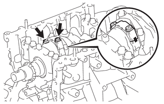
Remove the 2 connecting rod cap bolts.
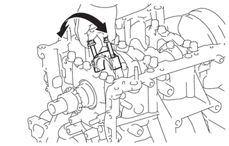
Using the 2 removed connecting rod cap bolts, remove the connecting rod cap and lower bearing by wiggling the connecting rod cap right and left.
- HINT:
-
Keep the lower bearing inserted to the connecting rod cap.
Clean the crank pin and bearing.
Check the crank pin and bearing for pitting and scratches.
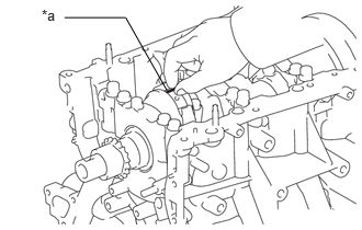
| *a | Plastigage |
Lay a strip of Plastigage on the crank pin.
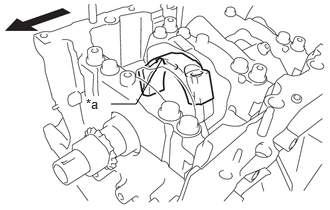
| *a | Front Mark |

|
Engine Front |
Check that the front mark of the connecting rod cap is facing forward.
Install the connecting rod cap.
- NOTICE:
-
Do not turn the crankshaft.
Remove the 2 bolts and connecting rod cap.
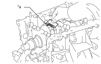
| *a | Plastigage |
Measure the Plastigage at its widest point.
- Standard oil clearance:
0.032 to 0.052 mm (0.00126 to 0.00205 in.)
- Maximum oil clearance:
0.070 mm (0.00276 in.)
If the oil clearance is more than the maximum, replace the connecting rod bearings. If necessary, inspect the crankshaft.
- HINT:
-
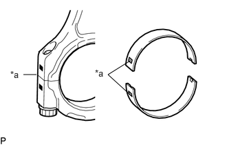 1.969,0.917 1.635,1.125 1.635,1.125 1.958,1.417 false 0.552,1.125 0.354,1.125 false 1.438,1.021 1.719,1.281 0.281,0.26 10 false *a 0.156,1.042 0.552,1.354 0.396,0.313 10 false *a
*a Number Mark
-
If replacing a bearing, replace it with one that has the same number as its respective connecting rod cap. Each bearing standard thickness is indicated by a number (1, 2, 3 or 4) marked on its surface.
- Standard Connecting Rod Diameter:
Mark Specified Condition 1 56.000 to 56.006 mm (2.20472 to 2.20496 in.) 2 56.007 to 56.012 mm (2.20500 to 2.20519 in.) 3 56.013 to 56.018 mm (2.20523 to 2.20543 in.) 4 56.019 to 56.024 mm (2.20547 to 2.20566 in.)
- Standard Connecting Rod Bearing Center Wall Thickness:
Mark Specified Condition 1 1.481 to 1.484 mm (0.05831 to 0.05843 in.) 2 1.485 to 1.487 mm (0.05846 to 0.05854 in.) 3 1.488 to 1.490 mm (0.05858 to 0.05866 in.) 4 1.491 to 1.493 mm (0.05870 to 0.05878 in.)
- Standard crankshaft pin diameter:
52.992 to 53.000 mm (2.0863 to 2.0866 in.)
- NOTICE:
-
Completely remove the Plastigage after the measurement.
3.REMOVE PISTON SUB-ASSEMBLY WITH CONNECTING ROD
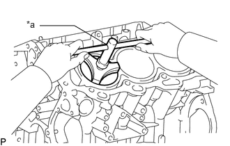
| *a | Ridge Reamer |
Using a ridge reamer, remove all the carbon from the top of the cylinder.
Push the piston, connecting rod assembly and upper bearing through the top of the cylinder block.
- HINT:
- ·
Keep the bearing, connecting rod and cap together.
·Arrange the piston and connecting rod assemblies in the correct order.
13041
4.REMOVE CONNECTING ROD BEARING
Remove the connecting rod bearings from the connecting rods and connecting rod caps.
- HINT:
-
Arrange the removed parts in the correct order.
13411
5.REMOVE CRANKSHAFT
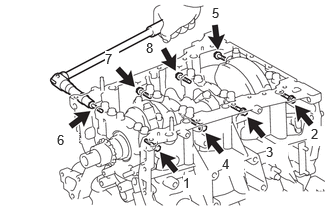
Uniformly loosen and remove the 8 crankshaft bearing cap bolts and 8 seal washers in several steps and in the sequence shown in the illustration.
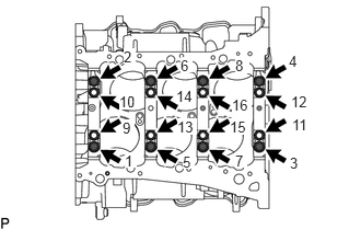
Uniformly loosen the 16 crankshaft bearing cap bolts in several steps and in the sequence shown in the illustration.
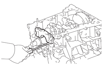
Using a screwdriver, pry out the crankshaft bearing caps. Remove the 4 crankshaft bearing caps and lower crankshaft bearings.
- NOTICE:
- ·
Push up on the cap slowly and evenly, alternating from the right and left side so that the bearing cap can be removed.
·Be careful not to damage the joint surfaces of the cylinder block and the crankshaft bearing cap.
Remove the crankshaft.
11702
6.REMOVE CRANKSHAFT BEARING
Remove the upper crankshaft bearings and lower crankshaft bearings.
- HINT:
-
Arrange the removed parts in the correct order.
11011
7.REMOVE CRANKSHAFT THRUST WASHER SET
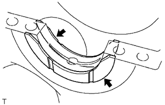
Remove the upper crankshaft thrust washers from the cylinder block sub-assembly.
13011
8.REMOVE PISTON RING SET
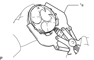
| *a | Piston Ring Expander |
Using a piston ring expander, remove the 2 compression rings.
Remove the oil ring expander and 2 side rails by hand.
- HINT:
-
Arrange the removed parts in the correct order.
13101
9.REMOVE PISTON SUB-ASSEMBLY WITH PIN
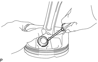
Disconnect the connecting rod from the piston.
Using a screwdriver, pry off the piston pin hole snap rings from the piston.
Gradually heat the piston to approximately 80°C (176°F).
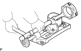
Using a brass bar and a plastic-faced hammer, lightly tap out the piston pin and remove the connecting rod sub-assembly.
- HINT:
- ·
The piston and piston pin are a matched set.
·Arrange the pistons, piston pins, connecting rods and connecting rod bearings in the correct order.
Using a gasket scraper, remove the carbon from the piston top.
Using a groove cleaning tool or broken ring, clean the piston ring grooves.
Using solvent and a brush, thoroughly clean the piston.
- NOTICE:
-
Do not use a wire brush.
15708
10.REMOVE NO. 1 OIL NOZZLE SUB-ASSEMBLY
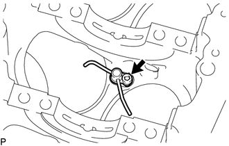
Using a 5 mm hexagon wrench, remove the 3 bolts and 3 No. 1 oil nozzle sub-assemblies.
Check the 3 No. 1 oil nozzles for damage or clogging.
If necessary, replace the No. 1 oil nozzle sub-assembly.
11.REMOVE CONNECTING ROD SMALL END BUSH
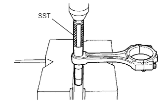
Using SST and a press, press out the bush.
- SST
- 09222-30010